A year ago, I bought a Toguard 5" Android dash cam with a backup camera. Several months ago, the backup camera died. Here's a picture of the camera that came with it (from the Amazon listing):
 |
| The camera that came with the Toguard DVR mirror |
I figured I'd search Amazon for a replacement camera. I found this one and thought it was the same.
 |
| Replacement backup camera |
 |
| Toguard backup camera, disassembled |
 |
| Toguard backup camera plug |
When checking the old camera, I found that it wasn't the camera that failed, but the cable. There were multiple breaks in the line, but nothing obvious from the outside.
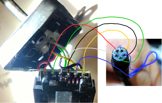
As far as I can tell, here is how the original backup camera for the Toguard DVR mirror was wired to the 2.5mm four conductor plug:
Tip: Red wire labeled DC, 5.75V power
Ring: White wire labeled DM, Video (signal ground, maybe?)
Ring: Green wire labeled DP, Video (signal high, maybe?)
Sleeve: Black wire labeled GND, Ground/reverse signal
____________________________________________________________________________
The replacement camera appears to be wired as follows:
Tip: Red wire, camera power
Ring: yellow wire, video signal
Ring: +12V power and white wire to LEDs
Sleeve: Ground wire and black wire to LED ground
Comparing the two wiring diagrams, you can see that plugging this into my DVR mirror and connecting power to the new backup camera was a bad thing. That put +12V on the video input. Keep in mind that the Android tablet only runs on +5V. I think the backup camera input is now fried.
 |
| Replacement backup camera plug |
 |
| Replacement backup camera, disassembled |
 |
| Replacement backup camera, showing the image sensor on the circuit board |

Thanks for the wiring diagram, really useful. Have you any idea how the Toguard camera triggers the DVR to switch to the backup camera?
ReplyDeleteI bought the Toguard dashcam and like you am trying to connect it to a different backup cam, I'd like it to automatically switch when in reverse but there's no obvious signal change on pins 2 or 3 on my oscilloscope when the reverse trigger is pulled high. It does work when connected to the DVR though.
Did you find out? Sorry if it is 2020 :D
DeleteThanks
Did you ever get a reaplacement camera to work? Looking at doing the same thing. Would it be possible to pull apart the camera and get it back together working based on your experience?
ReplyDeleteIt would have been possible if I hadn't hooked up the wrong replacement. It put 12V on the input and fried the camera input on the mirror.
DeleteI bought 2 replacement cameras (with 4pin) and none of them work. I still have another one (also 4 pin) that works with the mirror, so I'm gonna, try using your diagram, to see if i cam make them work. I will update the results.
Delete.
ReplyDelete5 pin cammera its a usb cam i use a usb cabele to connect it its realy warck tank you
ReplyDeleteHi
ReplyDeleteI'm I a similar situation where I want to use a different back camera flush mount, but don't seem to work as they as sold with RCA conecconn. Anyone have manage to hack this and rwgrofir non original camera? Tnx
Hi
ReplyDeleteI'm in a similar situation where I want to use a different back camera flush mount, but don't seem to work as they are sold with RCA connector. Anyone have manage to hack this and retrofit non original camera? Tnx
DM and DP (the white and green wires) are for the guide lines and "mirror view"(Flips images left and right). Those were the 2 loops you could snip to remove guide lines and switch view. +12v for LEDs, +5v camera, and a ground/trigger. Replace you sot23 mosfets/transistors are probably fried. Markings like "1AM" or "A2HS8" or something like that with 3 leads. Also try replacing the voltage regulators sot23-6 or sot23-5 6 leads or 5 leads.
ReplyDeleteDear, if DM and DP are the guide lines, wich wire is video signal? Thanks!!!
DeleteDoes Topguard make a suitable flush mount camera?
ReplyDeleteI believe the 12v input is for a signal from the reverse light. The unit will then show a lower portion on the camera’s image and display a red/amber/green distance grid.
ReplyDeletetq for ur studying..
ReplyDeleteThe 5 Pin camera is indeed a USB Camera.
ReplyDeleteThe 'DM' label means 'D-' or 'Data minus' and 'DP' means 'D+' or 'Data plus'
you are absolutely right. I have conected the camera to a pc and windows shows video.
DeleteHola, tengo un dvr mirror pero no he podido conectar otra cámara de tipo componente rca, según el diagrama de 5 pines del conector macho hembra 2 pines son cvbs+ y cvbs- pero no detecta la entrada de video, he conectado la salida componente de un dvd player LG y aún así no detecta, alguien sabe dónde conseguir una cámara compatible?
ReplyDeletehttps://ae01.alicdn.com/kf/HTB1meV5BWSWBuNjSsrbq6y0mVXaf/LEEWA-15m-2-5mm-TRRS-Jack-Connector-To-4Pin-Video-Extension-Cable-For-Truck-Van-Car.jpg
ReplyDeletehttps://ae01.alicdn.com/kf/HTB1zEiEtMKTBuNkSne1q6yJoXXab/LEEWA-10PCS-20m-2-5mm-TRRS-Jack-Connector-To-5Pin-Video-Extension-Cable-For-Truck-Van.jpg_q50.jpg
if you look at these diagrams it makes sense why Provident Engineering fried the monitor
EL MISMO PROBLEMA....SE QUE DE ELTRRS PLUG DE 2.5 MM SALE UNA SEÑAL DE 5VOLTS(TAL VEZ PARA ALIMENTAR A LA CAMARA?) ES COLOR ROJO 5VDC MIDE EN VOLTIMETRO
ReplyDeleteTAMBIEN EL SLAAVE...TIP R R SLAVE LA CUARTA CONEXION DEL PLUG PEGADO AL PLASTICO...ESE PIN ES TIERRA
BLANCO Y VERDE SEG Y TERCER PIN MIDEN 0.6 VOLTS( ES DONDE DEBE ENTRAR LA SEÑAL DE VIDEO ??)
ES LO QUE MEDI....TAMBIEN ESTOY CON E MISMO PROBLEMA...CASO ENCUENTRE LA SOLUCION LO ALZARE AL POST
Can 5 pin DVR reverse backup pin socket is convert into RCA reverse camera socket? By matching wirings. just like rear recordings gain from DVR when entering reverse gear can it works as a reverse camera.
ReplyDelete