Monday, April 24, 2017

Toguard Backup Camera Replacement?

A year ago, I bought a Toguard 5" Android dash cam with a backup camera. Several months ago, the backup camera died. Here's a picture of the camera that came with it (from the Amazon listing):
The camera that came with the Toguard DVR mirror

I figured I'd search Amazon for a replacement camera. I found this one and thought it was the same.
Replacement backup camera
I plugged it in and . . . nothing. Then I attached the power wires on the new camera. Still nothing. So I did a quick resistance check and saw that they were not wired the same. That kind of upset me, so I took it out on the cameras - both of them. I had to take them apart and see how each was wired. So on the long-shot that somebody's looking for a wiring diagram for both of these backup cameras, here ya go.

Toguard backup camera, disassembled
The wire from the camera to the DVR mirror is a five conductor cable, with a foil shield.

Toguard backup camera plug

When checking the old camera, I found that it wasn't the camera that failed, but the cable. There were multiple breaks in the line, but nothing obvious from the outside.


As far as I can tell, here is how the original backup camera for the Toguard DVR mirror was wired to the 2.5mm four conductor plug:

Tip: Red wire labeled DC, 5.75V power
Ring: White wire labeled DM, Video (signal ground, maybe?)
Ring: Green wire labeled DP, Video (signal high, maybe?)
Sleeve: Black wire labeled GND, Ground/reverse signal
____________________________________________________________________________

The replacement camera appears to be wired as follows:

Tip: Red wire, camera power
Ring: yellow wire, video signal
Ring: +12V power and white wire to LEDs
Sleeve: Ground wire and black wire to LED ground

Comparing the two wiring diagrams, you can see that plugging this into my DVR mirror and connecting power to the new backup camera was a bad thing. That put +12V on the video input. Keep in mind that the Android tablet only runs on +5V. I think the backup camera input is now fried.

Replacement backup camera plug
Now, look at the above picture. Can you think of any reason why it would be necessary to connect +12V to any tablet device's input? That doesn't make any sense to me.

Replacement backup camera, disassembled

Replacement backup camera, showing the image sensor on the circuit board
 Although the outside and the plugs looked very similar, these two cameras were in fact, very different.


Monday, April 10, 2017

1998 Accord Won't Start - Why you should RTM

My friend brought his car over because he was having problems where it sometimes wouldn't start. I said I'd take a look at it and didn't see anything obviously wrong. The OBD-II scanner didn't show anything wrong either. So I told him to just wait until it wouldn't start again and then we'll troubleshoot it.

It didn't take more than a couple days before he said it wasn't starting again. He tested for spark in that wasn't the problem. I then told him to open the throttle about 1/4 of the way and crank it for about five seconds, then smell the exhaust. He didn't smell any gasoline. Starting fluid helped for a bit.

I had him get down by the fuel tank and have someone turn the key to the on position. He heard the fuel pump run for a couple seconds. Check.

Our task was to find why the fuel injectors weren't firing. I had my OBD-II scanner plugged in, but it wasn't talking to the computer. I didn't see any relays labeled for ECU or PCM or the like. No fuses were blown.  I couldn't figure out why the engine computer wasn't powering on. I was turning the key off and on, watching the LEDs on the OBD-II adapter and saw no signs of communication.

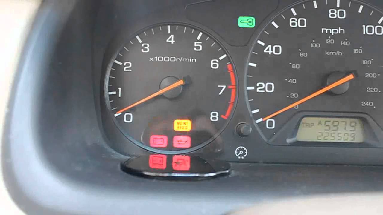
It was then that I noticed a little green light on the dashboard shaped like a key. When I turned the key to on, the light went on, then started flashing. "Hey, do you have a spare key for this thing?" I put the other key in and turned the key to the on position. The light came on, then went out and stayed out. "Hey, put that air intake back together under the hood." It fired right up.

And that's why you should read the owner's manual.

Picture credit: https://www.youtube.com/watch?v=hpG3Sazz3GA

Thursday, March 30, 2017

Replacing the screen on a ZenFone 2 Laser

The kid was having a bad day with his motorcycle repair. And then he dropped his phone, shattering the digitizer and breaking the LCD display and making his bad day even worse. Luckily for him, I had a spare phone. The spare phone was another ZenFone 2 with better specs. I let him borrow it while we waited for the replacement screen to arrive. 

It only made sense to get a $30 replacement display with the digitizer included to fix a $230 phone.


I watched a youtube video that showed how to disassemble the phone. The first parts were easy. Getting the back off, removing the battery, and the dozen screws (don't forget the one under the security sticker!) was easy. The back lifted right off after getting the screws all out.

The speaker module was stuck in with adhesive, so a little pulling got it out without too much trouble. The vibration motor came out without having to deal with any adhesive.

Watch a video that shows you how to remove the ribbon cables for the display and digitizer. You'll want to flip up the little plastic bar before sliding the connectors out.

Now, I don't know why the video shows them prying on the power switch. You don't need to pry on it or even remove it. Just leave it where it is. You can see on the left, it's still there in the picture below.


There is a white thermally conductive pad that you'll need to save or replace. I just added some thermal compound and stuck it back on when it was time to reassemble it.

If you've done this much, you're in for a treat. I recommend safety glasses for this next part. Prying on glass that's glued down could send tiny glass fragments flying. The best place to start is on the corner that's shattered. That way, you can get underneath the glass and separate it from the phone body. There's glue all the way around the entire edge. Separating the display from the phone is a tedious ordeal that will try your patience. And just now I realized that I should have used a hair dryer to heat it up. I don't do these very often, thankfully.


After getting the phone and screen separated, I removed the remaining adhesive from the phone because I didn't want any uneven edges. I'm sure glad I did a test fit before gluing the new screen in. I had to scrape out a corner so the new glass would fit in. The phone was bent on the corner that it dropped on, so I also had to bend that corner back.

You can see on the old screen (top) that the top right corner is bent. That's where the phone landed. The replacement screen (bottom) matches the old one.


I realized that the new screen didn't come with any replacement adhesive. I wasn't going to wait for an order of adhesive strips, so I decided to use contact cement. It's not the best idea, but it seems to be holding, at least for now.

Success! It worked! I got your phone fixed. Do you want to switch back? Nope, he said. "This one's battery lasts much longer." And that's why I like to have a spare phone, just in case.

Saturday, December 24, 2016

Crankshaft Seal Sleeve Repair

It didn't look like that big of a deal. It was holding oil when I installed it. But that little nick in the crankshaft pulley was enough to create an annoying leak. The dent was smooth to the touch, but it was right where the seal contacted the pulley. It didn't take long for the oil to start leaking. When the oil gets all over the wheel and you can see it on the side of the car, you know you have a problem. 

It didn't leak at idle. After the engine was warm, you had to hold the engine at about 3000 RPM for a bit and then you'd see oil draining from the seal.  

I had at least two options. One was to buy a new pulley. I didn't even want to look it up to see how expensive a new pulley would be. I found it, finally. I had to look under harmonic balancer, and it was actually only $69.43 at fordparts.com. But I decided to try a repair sleeve, sometimes called a speedy sleeve or redi-sleeve. 

I've never had to do a repair sleeve for a seal before, and now was my chance. I was pleasantly surprised at how easy it was. It was actually harder to install the seal than it was to install the repair sleeve. 


The instructions on the repair sleeve said to use a non-hardening sealer, so my best guess was Ultra RTV Black. I smeared that on the crank pulley and then used the included tool and a hammer to tap the sleeve into place. I just tapped lightly in circles until it was installed to the correct depth. 

Here's a picture of the pulley with the sleeve installed, and the tool sitting there on the pulley. I greased up the new surface to get it ready to install. The directions said that you could use the original seal and it would fit just fine. I made a preliminary test-fit before installing the new seal on the engine and verified that it fit. 


Getting the new seal installed into the timing cover was a little difficult. I had a wooden block with a hole in it for the crankshaft just for installing timing cover seals. I'd get it started and then it would start to go crooked. I'd tap one side and the other would pop right out. 

Sometimes it seems cars just want to try your patience. But I had more determination and showed it just who was boss. Sometimes it takes a firm smack in just the right place to get it to cooperate. I got the new seal in and re-installed the pulley with my pulley tool. No more leak. Yay!


Sunday, November 20, 2016

Strange Driveability Problems on a 2002 Nissan Sentra

I recently had the opportunity to work on a 2002 Nissan Sentra that had some strange symptoms. For just the solution, you can skip to the last two paragraphs. 

Here is a list of the problems:
  • Power loss at part to mid throttle
  • Hesitation
  • Rough idle
  • Random misfire on multiple cylinders
  • Hard shifts at part throttle
  • But it still had full power at full throttle
I got involved last spring when a neighbor needed help with a misfire. My OBD-II scanner showed it had a crankshaft position sensor code. I figured this was going to be an easy fix. I put a new crank sensor in and thought that was it. Nope. The check engine light came on soon after. This time it was for catalyst efficiency below threshold. 

The misfire situation melted the catalytic converter (as I discovered later). Just replacing the crankshaft position sensor didn't solve the strange driveablility problems listed above, so I cleaned the mass airflow sensor and checked the engine for signs of any vacuum leaks. I think I remember changing the spark plugs, but my neighbor thinks we didn't. 

I figured that since the car had 200k miles on it, it was time to replace the upstream oxygen sensors. That didn't help. I finally ran an exhaust back-pressure test and saw that the pressure was high. That in combination with the catalyst efficiency codes led us to replace the converter. The borescope images weren't really good, but showed what appeared to be melted honeycomb. 


Here's what it looked like after I got it off the car. 


Melted catalytic converter

After replacing the catalytic converter, I was careful to put the oxygen sensors back in the same places that they were in before. Even though the plugs were color coded and wouldn't fit in the wrong plug, I had a feeling in the back of my mind that it would still be possible to swap the oxygen sensors on the exhaust by installing them in the wrong hole. But I figured that if I was just careful not to swap them, we'd be ok. 

With the new converter, the car still had the same driveability problems as before. I was beginning to worry at this point. 

By the way, the new converter didn't match-up exactly on the lower mounting bolts. One hole was over a centimeter off, so I couldn't get the bolt in, but it'll work and pass inspection. 

If the engine was worn out, nothing else would matter much, so for a sanity check, I ran a compression test. Here are the results:

Cylinder 1: 122 PSI
Cylinder 2: 117 PSI
Cylinder 3: 120 PSI
Cylinder 4: 121 PSI

I cranked it with all the plugs in, but all the ignition coils removed. I cranked it on each cylinder for about eight compression strokes (until there was no more increase on the gauge). When re-installing the plugs, I used anti-seize compound on the spark plug threads, and dielectric tune-up grease on the inside of the plug boots. I Cleaned the MAF again, looked for vacuum leaks, and took it for a test drive. 

It should have run well, but there was no improvement. 

I connected my OBD-II scanner to it and saw that one bank's oxygen sensor was lean, and the other was rich. As the computer further leaned out one bank, and further enriched the other, I realized what the problem was. The upstream oxygen sensors were swapped. The blue connectors are for bank 1, and the green plugs are for bank 2. The outside two connectors are for the upstream sensors, while the inside two are for the downstream sensors. 

A quick google search got me the verification I wanted. Indeed, the upstream oxygen sensors were swapped. I put them in their correct places and took it for a test drive. Although it drove like a 14 year old car that needed shocks and struts, the engine was back to normal. 

I have no idea when the sensors got swapped, or if it was even my fault. I didn't verify that the sensors were correct, so that's on me. I just went off of where they were before. But at least it's fixed now. 

Friday, October 14, 2016

2008 Ford F250 Hydroboost Power Brake Unit Replacement

When I got the truck, I thought someone spilled something on the driver's side floor. I had no idea that it was power steering fluid from the power brake booster.

The entire job isn't too hard. It took around three hours. I'm slow. I was also back and forth helping a neighbor with brakes at the same time.

I figured I'd start with removing the fuel cooler / turbo pipe assembly. A couple hose clamps on top, banjo bolts for the fuel lines, and five mounting bolts later, it comes out as a unit. 


Again, I remembered to not forget that sneaky nut hiding behind the oil dipstick tube. There were a couple more small nuts holding the lower part of the bracket on. But these had worked themselves loose already. 

There, that wasn't too bad. Now to get the power booster out. 


 The hydraulic lines (in the picture below) weren't hardly even tight. 

There was adequate room, but you can remove the return nipple if you need to loosen or remove the line on the booster that it's blocking your wrench from getting at.

 I've un-bolted the master cylinder from the brake booster. There was no need to remove any brake lines.

 Next, I removed the four mounting nuts on the inside. I'm going to have to use laundry detergent and a hand-held carpet cleaner or something to clean the mess up from the power steering fluid.

 I had to take off this plastic clip so I could get to the other clip that holds the brake pedal on the push-rod.


 Here's how the brake light switch was mounted to the push rod and pedal (minus the yellow plastic clip). 

The metal spring clip.

Here's the plastic bushing thing that goes on there. Watch for this so you don't lose it.

And this photo of the brake pedal on the floor is just to give you nightmares. 

 New unit (left), and old unit (right). Notice that they didn't supply the push rod or even a new retainer. How did I get the retaining clip out? A little push here and pull there, with a twist here and turn there, and it finally came out.


And there it is on the new unit. Bonus on the patina finish, or rust, as we called it in Cleveland, giving the new unit that rustic feel.

Speaking of feel, the brakes felt a little better with the new power booster. 

Replacing the Power Steering Pressure Hose on a 2001 Honda Odyssey

Spending the afternoon working on a neighbor's car when I took the day off work because I'm sick is a sure-fire way to get in trouble with the wife.

I got a sore throat on Monday afternoon. It got so bad I didn't sleep nearly enough that night. So I took the day off work to recover. I usually take some essential oils to fix any sore throat before it can get a hold of me. But I was a little late this time. When those essential oils hit the sore spots in the throat, it really stings.

Then my neighbor called to say she dropped off her car for me to replace the power steering hose. I wasn't going to have time until maybe Friday, so I figured I'd replace it then. Besides, I told her on Sunday at church that I'd fix her car on Tuesday. How hard could it be?

Apparently three hours worth. I had to drop the sub-frame that holds the drivetrain down about an inch to get the hose in there.

The passenger side top motor mount needed to be removed to get a little more room. 

It looks like that motor mount needs to be replaced. 

I loosened the front mounting bolts, and removed the back ones and let the frame down with a floor jack. It stopped after about an inch. If I needed more room, I'd put the floor jack under it and find other things to un-bolt, like the struts. But that was enough room, barely.


This van needs both sway bar links replaced. I'd say these were well beyond their wear limit.