Saturday, December 24, 2016

Crankshaft Seal Sleeve Repair

It didn't look like that big of a deal. It was holding oil when I installed it. But that little nick in the crankshaft pulley was enough to create an annoying leak. The dent was smooth to the touch, but it was right where the seal contacted the pulley. It didn't take long for the oil to start leaking. When the oil gets all over the wheel and you can see it on the side of the car, you know you have a problem. 

It didn't leak at idle. After the engine was warm, you had to hold the engine at about 3000 RPM for a bit and then you'd see oil draining from the seal.  

I had at least two options. One was to buy a new pulley. I didn't even want to look it up to see how expensive a new pulley would be. I found it, finally. I had to look under harmonic balancer, and it was actually only $69.43 at fordparts.com. But I decided to try a repair sleeve, sometimes called a speedy sleeve or redi-sleeve. 

I've never had to do a repair sleeve for a seal before, and now was my chance. I was pleasantly surprised at how easy it was. It was actually harder to install the seal than it was to install the repair sleeve. 


The instructions on the repair sleeve said to use a non-hardening sealer, so my best guess was Ultra RTV Black. I smeared that on the crank pulley and then used the included tool and a hammer to tap the sleeve into place. I just tapped lightly in circles until it was installed to the correct depth. 

Here's a picture of the pulley with the sleeve installed, and the tool sitting there on the pulley. I greased up the new surface to get it ready to install. The directions said that you could use the original seal and it would fit just fine. I made a preliminary test-fit before installing the new seal on the engine and verified that it fit. 


Getting the new seal installed into the timing cover was a little difficult. I had a wooden block with a hole in it for the crankshaft just for installing timing cover seals. I'd get it started and then it would start to go crooked. I'd tap one side and the other would pop right out. 

Sometimes it seems cars just want to try your patience. But I had more determination and showed it just who was boss. Sometimes it takes a firm smack in just the right place to get it to cooperate. I got the new seal in and re-installed the pulley with my pulley tool. No more leak. Yay!


Sunday, November 20, 2016

Strange Driveability Problems on a 2002 Nissan Sentra

I recently had the opportunity to work on a 2002 Nissan Sentra that had some strange symptoms. For just the solution, you can skip to the last two paragraphs. 

Here is a list of the problems:
  • Power loss at part to mid throttle
  • Hesitation
  • Rough idle
  • Random misfire on multiple cylinders
  • Hard shifts at part throttle
  • But it still had full power at full throttle
I got involved last spring when a neighbor needed help with a misfire. My OBD-II scanner showed it had a crankshaft position sensor code. I figured this was going to be an easy fix. I put a new crank sensor in and thought that was it. Nope. The check engine light came on soon after. This time it was for catalyst efficiency below threshold. 

The misfire situation melted the catalytic converter (as I discovered later). Just replacing the crankshaft position sensor didn't solve the strange driveablility problems listed above, so I cleaned the mass airflow sensor and checked the engine for signs of any vacuum leaks. I think I remember changing the spark plugs, but my neighbor thinks we didn't. 

I figured that since the car had 200k miles on it, it was time to replace the upstream oxygen sensors. That didn't help. I finally ran an exhaust back-pressure test and saw that the pressure was high. That in combination with the catalyst efficiency codes led us to replace the converter. The borescope images weren't really good, but showed what appeared to be melted honeycomb. 


Here's what it looked like after I got it off the car. 


Melted catalytic converter

After replacing the catalytic converter, I was careful to put the oxygen sensors back in the same places that they were in before. Even though the plugs were color coded and wouldn't fit in the wrong plug, I had a feeling in the back of my mind that it would still be possible to swap the oxygen sensors on the exhaust by installing them in the wrong hole. But I figured that if I was just careful not to swap them, we'd be ok. 

With the new converter, the car still had the same driveability problems as before. I was beginning to worry at this point. 

By the way, the new converter didn't match-up exactly on the lower mounting bolts. One hole was over a centimeter off, so I couldn't get the bolt in, but it'll work and pass inspection. 

If the engine was worn out, nothing else would matter much, so for a sanity check, I ran a compression test. Here are the results:

Cylinder 1: 122 PSI
Cylinder 2: 117 PSI
Cylinder 3: 120 PSI
Cylinder 4: 121 PSI

I cranked it with all the plugs in, but all the ignition coils removed. I cranked it on each cylinder for about eight compression strokes (until there was no more increase on the gauge). When re-installing the plugs, I used anti-seize compound on the spark plug threads, and dielectric tune-up grease on the inside of the plug boots. I Cleaned the MAF again, looked for vacuum leaks, and took it for a test drive. 

It should have run well, but there was no improvement. 

I connected my OBD-II scanner to it and saw that one bank's oxygen sensor was lean, and the other was rich. As the computer further leaned out one bank, and further enriched the other, I realized what the problem was. The upstream oxygen sensors were swapped. The blue connectors are for bank 1, and the green plugs are for bank 2. The outside two connectors are for the upstream sensors, while the inside two are for the downstream sensors. 

A quick google search got me the verification I wanted. Indeed, the upstream oxygen sensors were swapped. I put them in their correct places and took it for a test drive. Although it drove like a 14 year old car that needed shocks and struts, the engine was back to normal. 

I have no idea when the sensors got swapped, or if it was even my fault. I didn't verify that the sensors were correct, so that's on me. I just went off of where they were before. But at least it's fixed now. 

Friday, October 14, 2016

2008 Ford F250 Hydroboost Power Brake Unit Replacement

When I got the truck, I thought someone spilled something on the driver's side floor. I had no idea that it was power steering fluid from the power brake booster.

The entire job isn't too hard. It took around three hours. I'm slow. I was also back and forth helping a neighbor with brakes at the same time.

I figured I'd start with removing the fuel cooler / turbo pipe assembly. A couple hose clamps on top, banjo bolts for the fuel lines, and five mounting bolts later, it comes out as a unit. 


Again, I remembered to not forget that sneaky nut hiding behind the oil dipstick tube. There were a couple more small nuts holding the lower part of the bracket on. But these had worked themselves loose already. 

There, that wasn't too bad. Now to get the power booster out. 


 The hydraulic lines (in the picture below) weren't hardly even tight. 

There was adequate room, but you can remove the return nipple if you need to loosen or remove the line on the booster that it's blocking your wrench from getting at.

 I've un-bolted the master cylinder from the brake booster. There was no need to remove any brake lines.

 Next, I removed the four mounting nuts on the inside. I'm going to have to use laundry detergent and a hand-held carpet cleaner or something to clean the mess up from the power steering fluid.

 I had to take off this plastic clip so I could get to the other clip that holds the brake pedal on the push-rod.


 Here's how the brake light switch was mounted to the push rod and pedal (minus the yellow plastic clip). 

The metal spring clip.

Here's the plastic bushing thing that goes on there. Watch for this so you don't lose it.

And this photo of the brake pedal on the floor is just to give you nightmares. 

 New unit (left), and old unit (right). Notice that they didn't supply the push rod or even a new retainer. How did I get the retaining clip out? A little push here and pull there, with a twist here and turn there, and it finally came out.


And there it is on the new unit. Bonus on the patina finish, or rust, as we called it in Cleveland, giving the new unit that rustic feel.

Speaking of feel, the brakes felt a little better with the new power booster. 

Replacing the Power Steering Pressure Hose on a 2001 Honda Odyssey

Spending the afternoon working on a neighbor's car when I took the day off work because I'm sick is a sure-fire way to get in trouble with the wife.

I got a sore throat on Monday afternoon. It got so bad I didn't sleep nearly enough that night. So I took the day off work to recover. I usually take some essential oils to fix any sore throat before it can get a hold of me. But I was a little late this time. When those essential oils hit the sore spots in the throat, it really stings.

Then my neighbor called to say she dropped off her car for me to replace the power steering hose. I wasn't going to have time until maybe Friday, so I figured I'd replace it then. Besides, I told her on Sunday at church that I'd fix her car on Tuesday. How hard could it be?

Apparently three hours worth. I had to drop the sub-frame that holds the drivetrain down about an inch to get the hose in there.

The passenger side top motor mount needed to be removed to get a little more room. 

It looks like that motor mount needs to be replaced. 

I loosened the front mounting bolts, and removed the back ones and let the frame down with a floor jack. It stopped after about an inch. If I needed more room, I'd put the floor jack under it and find other things to un-bolt, like the struts. But that was enough room, barely.


This van needs both sway bar links replaced. I'd say these were well beyond their wear limit.


Tuesday, June 28, 2016

Fun With Cam Sprockets and a Home Made Spanner Wrench

Start at noon, and be done by 6:00PM, right? I figured the timing belt replacement shouldn't take longer than six hours. I thought wrong.

It was going fine, although a little behind schedule by the time I got to the cam sprockets. I needed to remove the bolt so I could take them off and replace the cam seals. I tried my impact wrench on the front cam, while holding the sprocket with some channel locks. That didn't work. I needed a very large spanner wrench.


I checked youtube to see how other people removed the cam sprockets. I saw some videos where these guys made contraptions using the old timing belt to hold the sprocket. The belt broke on at least one of the videos. I was going to need something that wouldn't break the first time.

I found the Lisle Universal Cam Adjuster Tool for $42, but it looked too wimpy. The ATD Tools 8614 Variable Pin Spanner Wrench for $54 with only a 1 lb shipping weight was definitely not going to hold back the torque I needed.

I finally dismissed the idea of finding an appropriate tool at the auto parts store, or even at a hardware store. I've never seen a spanner wrench of the kind I was going to need. I needed a Tim "The Toolman" Taylor's kind of spanner wrench for this job.

Thankfully, Home Depot had the materials I needed to build my own for less than $30.

(1) 1/4" thick steel, 1.5" wide x 48" long
(1) 1/4" thick steel, 1.5" wide x 36" long
(3) 5/8" x 2" bolts
(4) 5/8" nuts
(6) 5/8" flat washers

I already had a stepper bit and a drill press, so drilling 5/8" holes into the steel was no problem. Here's the finished product.

Home Made Spanner Wrench

I didn't need the extra length on the 36" bar, and could have just cut 12" off the 48" bar and had plenty of leverage, but this worked and it looks like it'll be able to handle all the torque I can muster. Plus, I can maneuver the spanner wrench from one end using the extra length on the short bar.

 If you look closely, you can see that I used two nuts on the pivot, for hopefully obvious reasons.

Back to the timing belt job, Mom was waiting while I was working, so it had to get done that night. This spanner wrench worked very well. I was able to put my longest breaker bar on the bolt with the spanner wrench holding the sprockets and with some effort, broke the bolts free. After that, it was all routine. I replaced the cam and crank seals, the water pump, and got the new timing belt on.

There were no instructions specific to this application, and I never figured out why the mark for the crank on the belt was off by five teeth. The belt had white line marks that lined up perfectly for the cams, but the white line on the belt for the crank pulley was off by five teeth. It didn't line up when I flipped the belt around either. Oh well. It's probably because the belt doesn't touch the crank pulley at the mark when they're all lined up.

I lined up the cam and crank marks before pulling the old belt off and made sure the marks were lined up perfectly before pulling the pin on the tensioner. I tried to keep it quiet, except for when I had to tighten the crank pulley bolt with an impact wrench. At least the neighbors can be grateful that it wasn't them out under the hood until late.

As the time passed, I had to go slowly and carefully to make sure I didn't miss anything like filling the coolant back up before sending Mom on her way. I finally got done at 12:55 AM.

Tuesday, June 14, 2016

How to Change the CVT Fluid and Filters on a 2007 Ford Freestyle

We bought this car with about 124,000 miles on it. It now has about 126,000 miles. I checked the maintenance recommendations and they didn't say anything about changing the transmission fluid and filter before 150k miles - just check the fluid. Well, minimum maintenance cost isn't going to get you maximum life out of your car. So here we are.

The drain plug is easy. That's a 6 mm allen wrench. The fill plug is located right on the top of the transmission. It has a 3/8" square hole that your socket extension fits right into. After removing the air filter cover and air hose, you can see the fill hole right on top.

The fill plug is on the top, next to the sticker.

Here's the fill plug. It even has a nice, green o-ring.

Getting to the high pressure filter is a little more involved. You pretty much need to take out that motor mount.

Here's the motor mount that was in the way.

 Now we can easily get to the torx screws holding the filter in. There are three screws that need to come out. Then pull on the thing and pry a little until it pops out.


Did I mention that the fluid would drain out and you'd need a bucket? That fluid looks like it was due for a change. There's an o-ring on this housing that didn't come with my filter. So I re-used it. I hope it doesn't leak.


And here's the original filter with 126,000 miles on it. The thing should have been changed at half that many miles. The element is starting to collapse. There's the new filter next to it, just for comparison. I had to pry and pull on that filter to get it out because of the o-ring. The new one was just as hard to put in. I put some new CV fluid on the o-ring so it could actually go in.


The rest of the job is pretty much like a standard transmission fluid and filter change. Just make sure you buy both filters, and fill it up with CV fluid. I used Valvoline. Get six quarts, just in case you need some of that sixth quart to get it up to the correct level.

The dipstick has the normal indicators for fluid level.

Replacing the AC Compressor on a 2001 Honda Odyssey

At first glance, it doesn't look easy. Then when you get it unbolted, you're wondering how it's supposed to get out of there. It really is possible. You just have to lower the front frame a bit.
I loosened the two bolts on the front of the frame and removed a bracket that you can see isn't there in the video. Lowering the front of the frame about an inch or so was enough to squeeze the old one out and the new one in. I didn't show the jack supporting the frame on the other side, just to make sure it didn't bend the rear mounting bolts.


Monday, May 30, 2016

When That 20 Minute Repair Takes Four Hours

It was supposed to be a 20 minute repair job, a simple repair, nothing to blog about. I didn't even take any pictures. The drain valve on the fuel/water separator was broken. Only three screws held it in. Piece of cake, right?

So I had my bucket under the broken drain valve to catch the fuel. Of course, any work on the fuel system is timed to coincide with a full tank of fuel. It's Murphy's law.

The drain valve on my 2008 F250 6.4 Diesel had the lever broken off, so you couldn't drain any water out. I wanted this fixed so in case I ever needed to drain the water, I could.

I took out the three screws and grabbed my pick to remove the two o-rings. Fuel was draining into the bucket and it was getting a little messy with fuel running down my arm, but it wasn't anything I couldn't deal with. I had paper towels and a bucket. It was a little difficult to see the surface where the o-rings seat when fuel was constantly draining out of it.

I replaced the two o-rings, put in the new drain valve, and put it back together. One problem remained. It was now leaking. It wasn't leaking before my "repair". So I took it apart, shined a flashlight on it and saw that it was packed with dirt where the o-rings were. The dirt must have been what jammed the valve, causing the lever to break when somebody tried to open it. I cleaned it up with an old toothbrush. Again, diesel fuel was running down my arm. It's a good thing I buy those blue mechanic paper towels from Costco in the bulk package.

That old toothbrush was too soft. I needed a hard bristle brush. Now I know why they sell hard bristled toothbrushes. Nobody actually brushes their teeth with them. They use them for cleaning.

I thought I got it clean enough, so I put it back together, again. But it was still leaking. So I took it apart and compared the new o-rings to the old ones. The new ones were slightly smaller. Ok, a quick trip to the auto parts store was only 15 minutes away. I used to work at Checker Auto back in my college days. I knew where they kept them. I took the Freestyle because I didn't want to drive the truck with it leaking fuel.

By this point, I had drained and collected about five gallons of diesel fuel, but I didn't catch it all. Somehow, despite my best efforts to contain it, some fuel missed the bucket and was running down the driveway into my neighbor's lawn.

My neighbor, Phil, has the perfect yard. Mine is the kind of yard that drives people to organize those Satanic organizations called Home Owner Associations. I already had one oil leak go off my driveway into his landscaping rocks. Now I've got diesel fuel running into his lawn.

I can only imagine what diesel fuel does to grass. I'm scared. It doesn't just evaporate in an hour like gasoline does. Maybe if I fix his power steering leak for free, I'll remain on his good side.

I decided to try Autozone first. I showed them an old o-ring and they said that they no longer have the drawer of o-rings. You've got to be kidding me. Fine. I'll try O'Reilly. The guy at O'Reilly said they don't carry o-rings that thick. He pulled a set out from under the counter that looked like it came from Harbor Freight. I said, what about your drawer of o-rings? He said they discontinued the drawer of o-rings. I didn't know whether he just didn't know about it, or if the auto parts chains got together and decided to just make life difficult for their customers.

So I went down the aisle and found two assortment packs that appeared to have the right size o-ring. They were fuel-resistant too. Bonus! I had to get two packs because they only had one size of each in the pack. Ok. $14 for o-rings to get the truck to stop leaking isn't too bad. The drain valve kit was $58 from the dealer.

I measured the new o-rings I bought and the outer diameter was 0.515", and the thickness was 0.15", according to my micrometer. They appeared to be slightly larger than even the old o-rings. I thought we were in business. Again, I took it apart and brushed it clean with the toothbrush. These larger o-rings fit perfectly. Once again, diesel fuel was draining and running down my arm as I was cleaning the surface with a too-soft toothbrush.

I finally got it all back together. By this point, I decided it was staying together whether it was fixed or not. I was done. I even got a little rubber cap to put on the end of the drain spout in case it was still leaking. Guess what? It was still leaking - very slowly, like one drop per minute, but it was still leaking, and not out the drain spout. It was leaking around the drain spout, so my little rubber cap solution didn't solve anything.

I even thought I'd get clever and put a piece of scotch tape on the metal piece to serve as a gasket. Because for some reason, Ford decided to put a hole where the o-ring seats, and a hole that stops on the mating surface, without a gasket. Why? I have no idea, but it's leaking fuel. It looks like it was designed to leak fuel. So I left it with a plastic oil catch pan to catch the drips.

Wait. Did I put that pan there before, or after I took the truck to the auto parts store? Because I had one more project I could fit in before the day was over. I was a quart shy on changing the CVT fluid on the Freestyle, so I wasn't going to drive the Freestyle with it low on fluid. I had to take the truck. If the pan got run over, it's not going to work very well for its intended purpose.

I checked, and I put the pan down before I left. But I put it away and forgot to put it under again when I got back. That's just as well because with the way my day was going, the wind probably would have blown it away anyway.

Update 14 June 2016
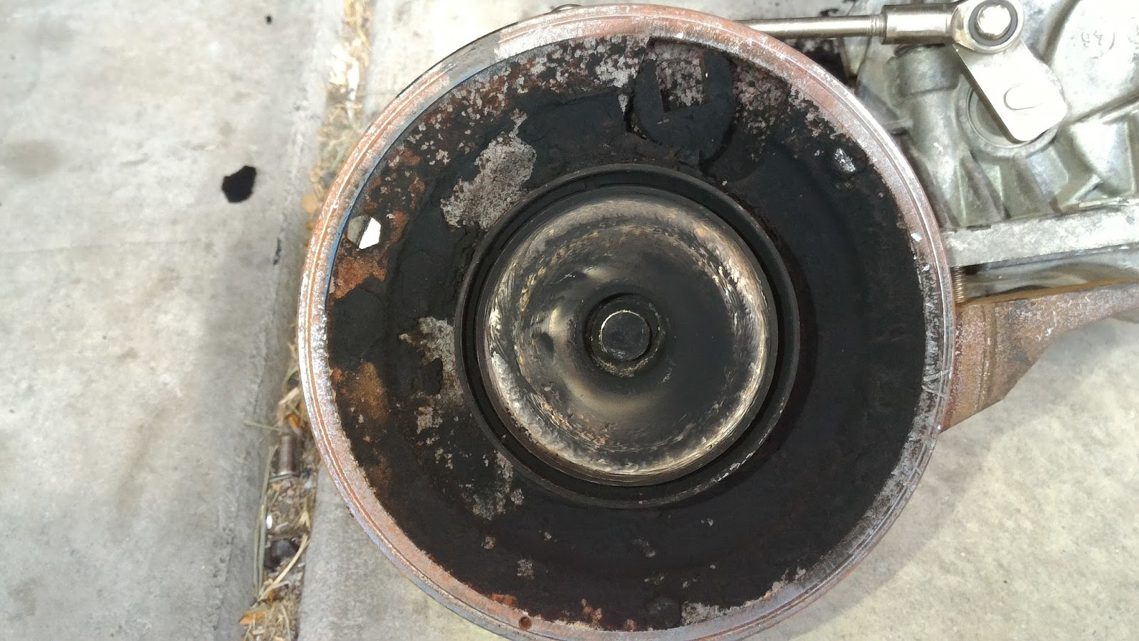
After trying to get back to this problem for a couple weeks, running at 1/4 tank or less, filling up 5 gallons at a time, I finally got back to it tonight. I had 35 miles left until empty, so tonight was perfect for this job. I parked uphill on my driveway and opened the fuel drain valve. After it drained, I was able to take a closer look and here's what I found.


If you're saying "wait, something doesn't look right", I'm with you. Ladies and gentlemen, this is an example of a casting error. No, not a mistake like Jar-Jar Binks, but where not enough aluminum got into the form when they cast the part. It's what we call in the industry a latent defect. That's where the defect doesn't show up until after the product is in the customer's hands.

When I was working on it earlier, I didn't realize that hole was not intended to be there. There was too much fuel draining and I was in a hurry. If my RTV doesn't fix the leak, I'll have to get another HFCM. Not fun for the wallet.

Sunday, May 22, 2016

DIY Project Phases - Excitement, Drudgery, then Victory!

When I take on a project, I'm usually pretty excited about it at first, but then there comes a time in nearly every big project when the excitement and motivation runs low. Take, for example, the half-way rebuilt transmission in my garage. It's been there as-is for almost two years now. I keep finding more important things to work on.

If there's a necessity, then I usually find a way to get things done. But for the non-essential projects, I'm easily distracted. So I've decided that most big projects go through several phases, among which are:

  • Excitement - dreaming and planning
  • Drudgery - doing what you planned
  • Victory - enjoying what you've accomplished

If I can manage to keep working through the drudgery phase, then I can enjoy the victory. I definitely went through drudgery during the turbo project. I had second thoughts about buying that truck. I wanted to just quit and leave it on the back burner for a while. I'm running out of back burners. It had to get done because it was going to be my daily driver until I got the transmission in the garage done. Yes, that one that's been in the garage for two years.

I was so excited to get the truck, but while I was working on it, I was asking myself "what was I thinking?" I really didn't need another project. But I persisted through the frustration and pain and can now enjoy it.

My neighbor wonders why I have to spend every weekend working on cars. He says he gets his cars to work for him, but I have to keep working on mine. He used to say it's because I drive Fords. Then he got one. See, neighbor? They're not so bad. There are several reasons I work on cars every weekend.

  • I have a bad habit of buying used cars that need help - because I can get them for cheap. I've learned that just because I can, doesn't mean I should. 
  • I like everything on my cars to work, but don't want to or can't afford to pay someone to do it for me. 
  • I like to keep my car clean, to the extent I have time - after all the essentials are done. 
  • I hate oil leaks. My truck's oil leak is driving me crazy. I haven't tracked it down yet. The Cougar's oil leak was toying with my sanity. I felt bad that the oil ran off the edge of my driveway into my neighbor's landscaping feature. 

One day I'll probably buy a nice used car. only a couple years old or so. I might someday even buy a new car. But Dave Ramsey says I should have a million dollars in the bank and pay cash for it. Yes, someday I'd like to buy a new car like that. The newest I've ever bought was the 1996 Thunderbird back in 2003, at 54,500 or so miles. It was a great car.

In short, don't give up. Finish what you started. Then enjoy the victory.

Thursday, May 5, 2016

How to Replace the Turbo on a 2008 Ford F250 6.4 Diesel

I don't often take selfies, but here's one for the record. That truck behind me was up for sale and for some reason I went back and got it after I thought it through and decided not to buy it. As I was working on it, I asked myself "what was I thinking?". As I was driving it, looking at the MPG, I again wondered, "what was I thinking?"
Me and my truck

When I replaced my turbo, I sure could have used a step by step guide on how to remove the turbo. It would have saved me a lot of time. So, to satisfy your curiosity, here's what I would do if I had to do this again. I hope I don't leave out any important steps.

At first glance, opening the hood, I didn't know what was what. I've never had a diesel before.

What's what under the hood
How to get at those awkward bolts
For many of the exhaust bolts, we'll need a flex head ratchet handle like the Craftsman 44815 because you can put a wrench on the handle and turn bolts facing the opposite direction, like this photo.

Here's how I'd do it if I had to again.
1. Disconnect both batteries and remove the driver's side battery.

2. Drain about 2 gallons of coolant from the radiator.

3. Remove the coolant reservoir / battery box assembly. It's held on with four bolts and some hoses. There's a vacuum reservoir on the bottom of the battery box with a vacuum line attached to the small port. You need to pull the wire retainer clip from the coolant hose end to remove it from the reservoir. Be careful not to bend the clip so you can reuse it.
Battery box / vacuum reservoir / coolant reservoir

4. Remove the fuel cooler / crossover tube assembly and mounting bracket as a unit:

Disconnect the fuel lines, drain the coolant, and disconnect the coolant lines.

I could have used this guide when I started. It would have been easier to get the coolant reservoir out of the way before this step. Remove the nuts from the three studs at the bottom center of the above picture. The oil dipstick is bolted to the stud on the left (towards the front of the truck). Remove that bolt, pull it off and there's another nut underneath you need to remove also. Then remove the two nuts on either side that hold it to the top of the valve cover. Slide the assembly toward the driver's side. Be careful not to damage the air seals. The air tube from the low side turbo can be pulled out.

The top right stud holding the fuel cooler assembly also holds an exhaust pressure sensor?

The top left stud for the fuel cooler mount appears in this photo next to the hose clamp for the intercooler.

Bottom bolts holding on fuel cooler assembly and oil dipstick

There's the intake side of the high side turbo. It wouldn't turn by hand. Wait 'till you see the other side.

5. Spray penetrating oil on all the exhaust bolts on the back of the turbo assembly. Remove the small exhaust tube with the sensor on the top and set it aside.

6. Remove the air filter assembly. Loosen the clamp to the low side turbo input. Remove the clamp on the hose going to the oil fill thing. Disconnect the plugs to the air filter monitor and MAF sensor. If the assembly doesn't lift out, there are two bolts supporting the mount: one by the battery, and one by the air intake. This picture is after I removed the turbo.


7. Remove the two banjo bolts that attach the oil supply lines to the turbos. Then remove the four bolts holding the heat shield on. These were rusted and I broke the one that I couldn't access with my electric impact screwdriver. Remove the heat shield. It'll bend a little.


8. Disconnect the exhaust pipe between the EGR cooler and the back of the turbos (7 bolts). This won't have enough room to come out, but you can move it around to access the other bolts you need to get to. You need this pipe out of the way to get at the six bolts holding the exhaust inlet pipes on the back of the turbo assembly. There's a mounting bolt in the middle of the pipe. Get this one from under the truck. Try a 6 point 10mm shallow socket on a 6" wobbly extension attached to a U joint, attached to a long extension to your ratchet handle. For all the 10mm bolts on the exhaust, use a six point socket. Do not use a 12 point socket on any of the exhaust bolts. That may strip them.

9. Remove the six bolts holding the two exhaust pipes on the back side of the turbo assembly. You'll need to get creative with your flex head ratchet. You need to be able to put a wrench on the end of the ratchet handle, so the Craftsman 44815 works pretty well here. Then remove the exhaust pipe from the back of the low side turbo. Don't bend the clip on top. It holds the pipe in place while you clamp it. Lift the pipe up and back. You probably want help here.

10. Remove the two main bolts holding the turbo assembly to the engine. In this picture, I'm on the front bolt. The other one is directly behind it. Don't remove the 10mm nut holding the high side turbo's oil return line down.

Removing the front mounting bolt for the turbo assembly

The two bolts and brackets that hold the turbo to the top of the engine

11. With all the exhaust bolts out and the two main mounting bolts out, you'd think you can just remove the turbo. Well, maybe, and maybe not. There are two pins on the bottom of the turbo that may be a little tight or rusted. First of all, the turbo assembly weighs about 80 pounds. So I used a shop crane to try to lift while I used a pry bar. I probably had too much tension with the shop crane which made the pins bind.
The pins are under the high side turbo. If you lift front and back at the same, straight up, you may be able to get it off easier than I did. Keep in mind, it weights 80 pounds. Here's a shot of the bottom side, looking from the back side after I removed it.

Bottom side of the turbo assembly, with the low side turbo on the right

Here's where the turbo was. You can see the two oil return passages for the low and high side turbos. Be sure to replace that o-ring on the high side turbo's oil return. The heat from the turbo cooks it and then it starts leaking. 

Here's what the turbo mounts to. There are two threaded holes for the bolts, and two holes for the pins.

Have fun getting those exhaust bolts off. Good luck.

Engine compartment after removing all that stuff

I took the turbo out by moving it towards the driver's side, with a shop crane lifting it.

The turbo assembly, suspended from a shop crane. A shop crane with a longer reach would have been nice.

12. I had to use my press to separate the variable vane control from the turbo. It was in there pretty tightly.

Here's my press setup. The punch started to bend, so I replaced that with a 5 mm deep socket and tried again.

Here's my first setup for pressing out the control linkage for the variable vanes.


To put it back on the new turbo cartridge, I oiled it and pressed it in with two pairs of pliers. Then I re-attached the E-clip.

So, what did I find?
That's some nasty buildup. Wait, why is the turbofan broken off?

There's a turbo fan that broke off the shaft, and a lot of soot buildup. Here's where the turbo fan was supposed to be.

Exhaust side of the old turbo, missing the fan.

The fan blades got pretty chewed up.
After cleaning up the variable vane stuff
New turbo cartridge, exhaust side

New turbo cartridge, intake side

I made the mistake of being too easy on the throttle after I got it all back together. So it turned on the check engine light for P132B (boost levels not achieved during learn cycle) and P2263 (turbocharger boost system performance). I was trying to get good gas mileage. My truck was telling me not to take it so easy. It'll get up and accelerate faster than any other car I've owned, but it gets 13 MPG.

Update Sept. 2017

I didn't replace the o-ring on the high side turbo oil return when I did this job. It was leaking about a quart every 300 miles by the time I finally took the turbo off again and replaced both the oil return o-rings on the high side and the weird seal on the low side. I was wondering if the two turbos were designed by two completely different engineers because they're so different.