Monday, December 21, 2020

1999 Cougar Engine Swap

When looking for a cheap, small car, I decided that, for the money, I could find an engine for the Cougar for much less than buying a working car. You might ask why the Cougar needed an engine after this repair. Well, the brand new timing chain tensioner that I installed failed. That allowed the chain to slap on start-up and the plastic chain guide broke and got ground up into the oil pan. That clogged the oil pickup screen and starved the engine of oil. I did failure analysis for fun. Ok I was trying to see if the engine could be saved. I fixed it and it worked fine for a few miles until it developed a rod knock.

So when I saw a 1998 Contour for sale, I knew I found an engine for the Cougar.  I could have replaced the power steering rack on the Contour and drove it, but then how exciting is a four door automatic when I could have a five speed coupe? 

I was going to help my son do the engine swap so he could drive the Cougar, but he was borrowing my Thunderbird to get to work and he decided it would be easier to just buy my T-bird from me than do the engine swap. Deal. I'll swap the Cougar engine and drive it. Looking back, I think he might have done the smarter deal. But mine will be more fun . . . after a lot of hard work.

I figured it shouldn't be too hard to swap an engine. I was thinking it would only take one day to remove the Cougar engine, one day to remove the Contour engine, one day to swap, and one day to put it back together. Just unhook stuff, unbolt stuff, use the engine crane and within a few days, there you go! I wish it was that easy. I seem to always underestimate the time it takes me to do these projects. Here's how long it actually took with life happening between Saturdays and evenings working on the car.

September 21

I was excited to start this project. I made good progress unhooking stuff.

September 22

Still highly motivated and making good progress. I dropped the engine out the bottom. (I lowered it with my shop crane.) 

Projects like this take less time in my head than in reality. I never account for things like broken bolts, broken drill bits, and needed replacement parts.


September 26

Raise the car higher and slide the engine out the side. This should have been done on day two, but it's ok. I'm not too far behind schedule. It's still warm enough outside. 

And pull the engine off the transmission.

October 1

Take pictures of the donor engine before unhooking everything.  

October 9

Drop the engine out of the Contour. Where did the time go? I was supposed to be done with this project in no more than three Saturdays with working on it some weekday evenings.

October 13

The sub-frame bolts kept turning the nuts because of the rust. There was a metal grate and sound absorber over the nuts, but it wasn't removable without cutting through it. So I had to cut through the floor to access the nuts and hold them with vice grips.

Pulled the Contour's engine out the side.

And when you forget to drain the transmission fluid, it goes all over the driveway.

October 14

Pull the Contour's engine off the transmission.

In addition to just swapping the engine, there were things that needed attention. 

  • Replace the crankshaft oil seals, front and rear.
  • Replace passenger side CV output shaft seal.
  • Replace the clutch disk. 
  • Swap power steering pumps. (The Contour's PS pump ran dry for who knows how long.)

Pre-Task Plan

Re-assembly is where you don't want to forget anything like a rear crank seal, so I decided to make a list of things to do, in order, to get the engine in. I didn't expect the list to be this long.

  1. Replace rear crankshaft seal.
  2. Install new clutch disk.
  3. Tighten axle mount bolts on rear of engine.
  4. Install Bottom Engine Mount bolts
  5. Install starter
  6. Replace P/S pump
  7. Replace front crankshaft seal
  8. Clean CV splines and reinstall CV shaft
  9. Re-install engine wiring harness
  10. Fix speed sensor wire (it broke)
  11. Work exhaust manifold bolts in case cats need replacing
  12. Slide engine under car
  13. Tie up all loose connections on engine before lifting
  14. Lift engine
  15. Install four chassis bolts
  16. Bolt in top Engine mounts
  17. Connect computer harness & ground wires
  18. Connect power steering reservoir supply & return hoses
  19. Engine mount ground cable
  20. Bolt in struts
  21. Install fender shrouds
  22. CV axle nuts, Brakes, strut, sway bar links
  23. Connect steering linkage
  24. Shifter cables
  25. Clutch hose
  26. Brake hoses
  27. Connect evap vacuum hose 1/8"
  28. Connect evap hose 3/8"
  29. Climate control vacuum hose
  30. Brake booster vacuum hose
  31. Connect fuel supply & return
  32. Connect wiring harness on driver side
  33. Accelerator & cruise cables
  34. Battery ground cable
  35. Install radiator/fan assembly
  36. Radiator hose assembly
  37. Fan wire & other wire (Yeah, I don't know what it connects to at the moment.)
  38. Connect heater hoses
  39. Connect the three coolant reservoir hoses
  40. Install P/S cooler
  41. Mount temperature sensor
  42. P/S fluid
  43. Air filter box
  44. Air filter & hose, connect MAF sensor, PCV hose
  45. Install O2 sensor to replace the one I broke.
  46. Re-install exhaust heat shield
  47. Body ground cables
  48. Install battery (and then take it out again because it was in the way)
  49. Engine oil & filter
  50. Mount exhaust
  51. Re-connect fender rods
  52. Bleed clutch
  53. Grease ball joints
  54. Replace sway bar links
  55. Replace brake calipers
  56. Bleed brakes
  57. Wheels & torque lug nuts
  58. Top off transmission oil
  59. Install new AC accumulator
  60. Evacuate and re-charge the AC. (Need to add another 0.2kg R-134A because it only took 0.55 kg and won't run when it's this cold)
  61. Install new windshield wipers
  62. Install air dam deflector
  63. Get new tires
  64. Install DVR dashcam
  65. Fix brake sensor wires
  66. Replace idler pulley
  67. Flush heater core

 October 17

Removing the rear crankshaft seal works better using a screw than using the actual seal puller tool. There's less risk of damaging the crankshaft sealing surface with the screw method than with the seal puller. I drilled into the metal part of the seal and used a claw hammer to pry off the old seal. You can see the seal puller in the top part of this photo. It doesn't work. It's pretty useless.

It looks like there's only one way the flywheel can go on to make all the holes line up. I like that. It mistake-proofs the assembly. The Japanese call that poka yoke.

I found that it would have been easier to connect the engine and transmission if I had two engine hoists. Instead, we had the engine on the hoist and two-person-lifted the transmission to connect it to the engine. It was still way easier than trying to mate the two with the engine in the car.

Ouch!

When I was trying to pull the CV shaft out of the wheel knuckle, as soon as I got it clear, I smashed my finger tip between the CV shaft and the brake caliper. That stinkin' hurt. I was doing my best not to say bad words. "Sheesh, farmin' dog meat! That hurt!" I felt through the glove for any broken bones. No blood. Seems ok. It'll probably leave another mark on my fingernail that'll show up in a week. Amazingly, no mark. But there was a mark on that same fingernail from an injury a week or so earlier that I can't remember. 

"Dog meat" is my curse word. My son questioned that phrase when we were working on a car together. Something happened and that's what came out of my mouth. 

November 3, 4, 7

Installing the engine, transmission, sub-frame assembly. It doesn't look like it, but there was enough room to slide the engine in from the side under the fender. From there I used the shop crane to lift it into place.

The engine is finally in place. Notice that I moved the jack stands before putting all that additional weight on them.


November 11

I was about to connect the throttle cable when I realized it didn't match up. Had to swap the throttle assembly & clean the EGR passages while I was in there. Don't want all that carbon build-up to trigger the check engine light. Been there done that. I got the insufficient EGR flow trouble code before on the old engine.

November 14, 17

Install radiator etc. 

November 21

Back when I tried to unbolt the exhaust on the Contour, three studs on the exhaust pipe broke off. So I was trying to drill out the broken studs when a drill bit broke and sprung back and hit me hard enough to draw blood (injury number two on this project).

Then after all that, I was mostly done with drilling out the broken studs when I realized I had the wrong pipe end and it didn't match up with my catalytic converter. All that work drilling out those studs was for nothing. I had to swap in the exhaust pipe from my old engine.

November 28

Replaced engine oil & filter. 

So I went to unbolt the exhaust pipe and broke two more studs because they were seized. I had some cheap drill bits and spent a good part of another day trying to drill them out. Finally I went to the hardware store and got a couple good drill bits. I don't know why I didn't do that in the first place. It would have saved so much time.

December 5

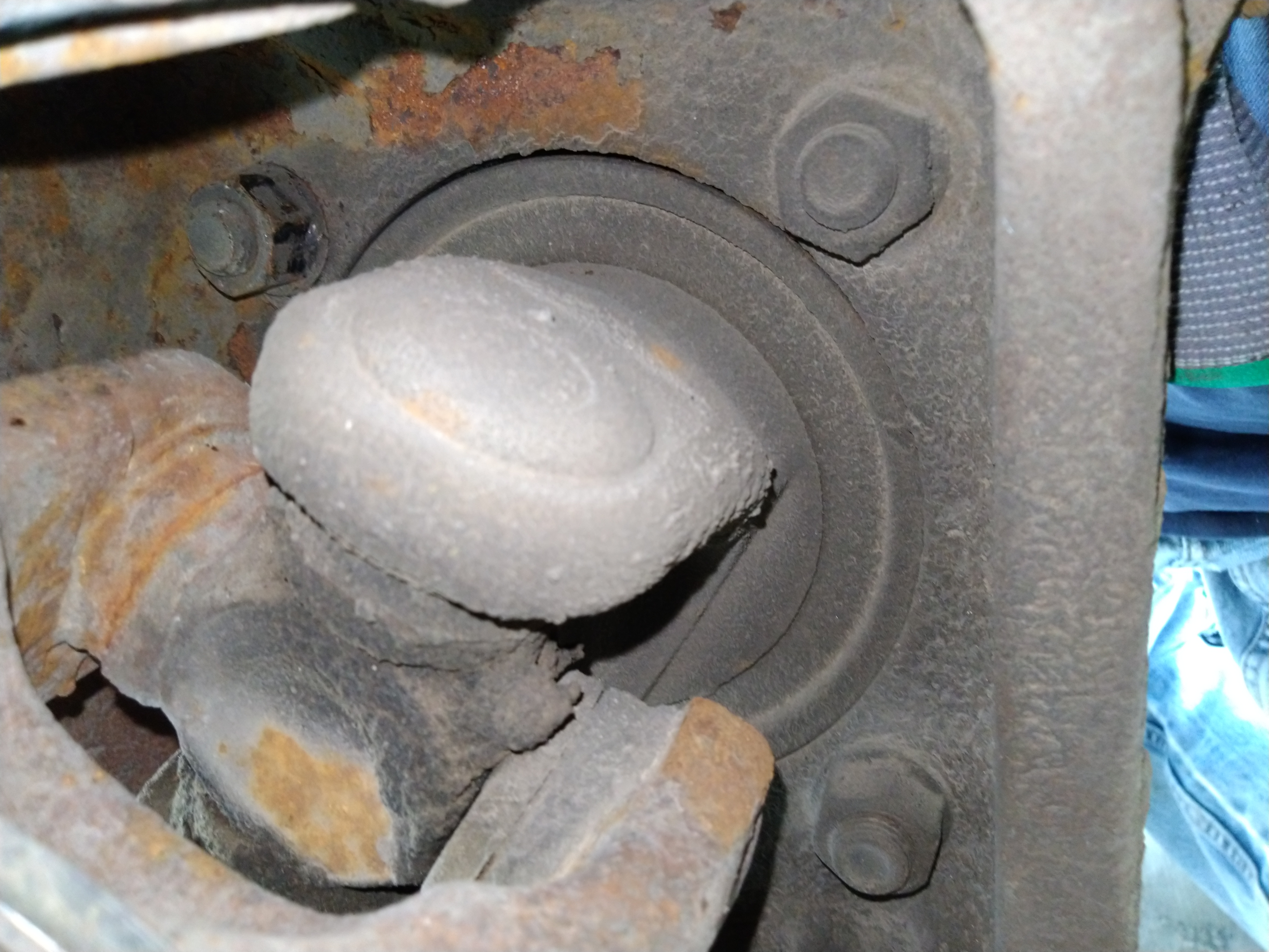
Install new sway bar links. Install new rear catalytic converter. Here's how I found the old cat was bad. The honeycomb structure was deformed from intense heat due to a misfire. Here's what it looked like on the inlet side. When I saw this, I wasn't going to put it back on. Maybe that's why the old engine was so weak.

Here's what the new catalytic converter looked like.

December 14

Which Brake Size Do I Have?

I tried to open the bleeder valve and broke it off because it was seized. Then I tried to open the bleeder valve on the other caliper. It also broke off. So I decided I would order new calipers instead of rebuilding these. The parts listings showed two different sizes of rotors: 260 mm or 278 mm. So I measured my rotors and they were 260 mm. I ordered the calipers for 260 mm rotors. So far, so good, right? 

When the calipers arrived, I removed the old ones only to find that someone put the smaller rotors on when it should have had the larger rotors. Thanks to that mistake (not mine!), now I have all the hardware for the 260 mm brakes instead of the 278 mm brakes.  

I'll have to order new 278 mm rotors and swap the caliper mounting brackets to go back to the original brake size. But not today.

December 15

Trip to the DMV to get temporary tags.

December 19

Air up the tires. Replace wiper blades. Air Conditioner - replace the accumulator, evacuate and recharge it. 

December 21

Got a set of new tires at Discount Tire. Still no check engine light, so before taking it to get emissions tested, I'll use my OBD-II scanner to make sure it's ready.

How Long Did it Take?

That project took about 13 weeks - at least eight Saturdays and twelve weekday evenings.

This is why old cars like this go to the junk yard instead of getting new engines. Sixty hours of labor at $60/hour would be $3600 in labor costs. Blue book value on this car isn't even $1000. So why did I even do this? I'm cheap and didn't want to spend that kind of money on another car right now. Besides, work is good for the soul and builds character. 

Oh yeah, and I had to prove that I could finish a difficult project because there's a Talon transmission that's been in my garage for seven years, still not finished.

Differences

This information is just for anyone else interested in this kind of engine swap. Here are some things that were different on the Contour compared to the Cougar engine:

  • Throttle linkage / throttle assembly 
  • Coolant temperature sensor
  • Rear catalytic converter
  • Exhaust pipe between all three catalytic converters
  • The aluminum plate between the engine and transmission has an access hole in the  automatic transmission version, but not in the manual version.
  • The manual trans uses a different bolt hole in the engine oil pan than the automatic, but there are two holes in the engine oil pan on that side, so the oil pan works for both auto and manual transmissions.


Thursday, November 26, 2020

Are Plastic Wheel Chocks Safe?

I went to Wal Mart looking for a wheel chock for my car. I asked an employee where they were because I couldn't find what I was looking for. When he pointed out this one, I knew why I couldn't find it. I was looking for a black rubber one. I had no idea they made plastic wheel chocks. 

I scoffed at the idea and was walking away when I got the idea to test it. I can afford to waste $3.47. So I went back and picked it up. Since they sell these in their automotive section next to the jack stands, I deduced that there were some people that would try to use these on a car. The label says don't use on tires larger than 21 inches. If you have a car with tires 21 inches or less in diameter, you don't have a car. You have a go-kart. 

Besides, would you trust your life getting under a car supported by a plastic wheel chock? Me neither. 

I put the chock in front of my pickup truck and let it roll down the driveway. Check out the results.


Monday, September 7, 2020

Front Axle U-joint Replacement on a 2008 F-250

Here's how I replaced the front axle, right side u-joint on my 2008 F-250. I would call it a success. If you need to do the same job, maybe you can learn from my mistakes. Got a day off? This is what I do on my days off to avoid a car payment.

Some tools required: hydraulic press and accessories, T-27 torx bit, 21mm deep socket, breaker bar, #6697 seal install tool, caliper hanger (bent coat hanger), big hammer, grease gun, big snap ring pliers, knee pads, 7/16 bolt & washer & nut to remove the inevitably stuck rotor, 5mm hex wrench, crow bar, and a healthy dose of patience.

Here's where we'll start, with the axle on a jack stand and the other three wheels chocked. 


Here's the old u-joint. I'm replacing it now so I don't have to do it in the middle of the winter when I need my 4WD to work.


I removed the brake caliper and hung it up using a specialized brake caliper hanging tool . . . made from an old wire coat hanger.

The brake rotor was super stuck. I shouldn't have, but I tried hitting it with a hammer to get it off. That is the wrong way. I should have done the bolt method from the beginning. I stuck a bolt through the caliper mounting hole and tightened the nut to push the rotor off. (See photo below.) After the one side broke free, I rotated the rotor 180 degrees and repeated. This worked really well.


With the rotor off, the hub was next. But it could have come off before the brakes. A T-27 torx bit removed the screws. Interesting fact: you see the FORD lettering on the locking hub? The letters are actually vents for the vacuum-operated hubs.

I didn't have to pull too hard to get it out. The grease doesn't look very pretty and it will need to be cleaned off and re-greased. It looks like these auto-locking hubs can't be re-built. If you break the plastic, you may need to buy a new locking hub.


To remove this lock ring, you definitely need a proper set of snap ring pliers. You need to put some muscle in it to spread it wide enough to come off. You may want to do this step later after pulling the axle shaft out. Keep reading.


This is a view of the back of the wheel knuckle. These four nuts need to come off to pull the bearing and hub assembly out. 


 But first, remove the wheel speed sensor. It needs a 5mm hex wrench.


 Be careful not to bend the brake shield. With a little prying and wiggling, the hub will come out.


Here's the big seal that needs to come out. But you can pull the axle shaft out as-is. I made a mistake and tried to pull the seal out first. The seal will come out with the axle.


Here I have a crow-bar stuck through the u-joint space with a socket on the left end for extra leverage. After a bunch of heavy duty yanks like this on the crow bar, the seal popped out along with the axle shaft. It wasn't easy.


 I tried my old way of drilling a hole and putting a screw in it and yanking it. That didn't work too well. The screws just popped out of the holes. It was kind of a waste of time.

I bet somebody will tell me that you can leave the snap ring in and pull the wheel hub and axle shaft out all at the same time, and then remove the snap ring later. That should save some effort if you have a big slide hammer.

With the axle shaft out, it's time to replace the u-joints. This next photo is a close-up of the inner clips. They weren't very easy to get out. I took out two clips and figured I'd separate the shaft and then remove the other two clips later.

Here's my setup on the press. A 36mm 12 point socket fit right over the caps. This 20 ton press has come in handy many times. It's so easy to use, I saw that my son had figured it out years ago when I saw a very flat Hotwheels car in the garage.


It took a decent amount of pressure on the 36mm socket to pop this cap out.

Moving to the other two u-joint caps, I was having a harder time and was wondering why the caps wouldn't budge. Then I realized I forgot to take out the retaining clips on this side. Once I took those out, it was easy enough. See that slot cut in, just behind the splines? That's for air to go through to lock the hubs.


 After cleaning up the yokes, it's time to put the new u-joint in.


I popped two caps off and put one in the yoke.


Then I put the u-joint through the open end and into the cap. This is why you want the yokes clean because I bet your clean grease will touch the yoke, unless your skill at the game "Operation" is expert level. Then I placed the other cap over the other end and used my press to push the caps in place. I made sure to put the grease fitting towards the inside of the vehicle so it's accessible.

After installing all four retaining clips, I gave each side of the yokes a good whack with the hammer to press the caps outward so the u-joint ends don't rub on the caps.

The new dust seal (SKF 16510) looks nothing like what's left of the old one. Not sure what happened there.

Here's the new dust seal installed in the axle. I cleaned off the axle with a wire brush on a drill. Then I greased the entire axle shaft so it would slide on the dust seal. My seal installer set came in handy for this dust seal.

Again, I did things out of order. I installed the axle shaft before installing the big seal. But at least I know it fits in the new dust seal.

Here's the new seal (National 710685) that's going to go on the shaft. I used the seal installer tool to install it on the axle shaft before installing the axle shaft.

Here's the seal installed on the axle shaft before installing it in the hub. I used the same seal installer tool for both steps to install this seal.

This seal installer tool is a must-have for this job. I just had to hit it with a big hammer until it was flush. It didn't take a huge amount of force. It was about what I expected for a seal that size. But I did grease the edge of the seal, for better or worse. I'll probably find out later if that was a bad idea. Maybe I should have used WD40 instead of grease on the outer edge.

I didn't get a new (SKF 5C3Z4) axle hub o-ring to replace the yellow o-ring in this picture. It should be ok though. I greased the surface where the o-ring goes and bolted the bearing/hub assembly back in.

Getting the snap ring back in took many tries. I finally figured out that I needed to hold the axle outward with my crowbar and then it went in. Then I realized I installed the hub without the brake shield. Time to take stuff back apart.

I removed the snap-ring on the first try, unbolted the hub, put the brake shield on, bolted the hub back on, and then God must have accepted my sacrifice and we got the snap ring back on in one try.

It looks like these hubs aren't rebuildable. I'm sure I'd destroy the plastic if I attempted to bend the metal out. The (Dorman 600-249) service kit comes with two o-rings, a gasket, and three replacement screws. I didn't find where the second o-ring goes.
So I added some new grease to the hub and installed it.


From this point, all I needed to finish was re-mount the brake rotor, brake caliper, and wheel. 

It took me about 8 hours, a full day of work. It wasn't as bad as I thought. I checked Amazon and saw that I bought the seal install tool almost two years ago. I was dreading this repair, thus the procrastination.

Price breakdown

Moog 374 u-joint: $31.79
Axle dust seal SKF 16510 $7.20
Dorman 600-249 hub lock service kit: $19.08
SKF 5C3Z4 axle hub o-ring $4.92
National 710685 the big seal $31.79
#6697 Seal installer tool $85.26
Exercise patience and gain confidence $priceless

Total: $180.04 + tax and shipping

If I paid someone else to do it, I think it would be around $800.


Sunday, September 6, 2020

Poka-yoke Gone Wrong

Polka yoke?

Poke a yolk?

Pokey yoke?

Po ka yo ke?

"Poka-yoke" is a way to prevent mistakes. One way to do this is to have engineers design parts that can't be assembled incorrectly. Or, in the case of aftermarket auto parts, they make parts that can't even be assembled at all.

Here's an example from a 2007 Ford Freestyle. I needed to replace the passenger side lower control arm because the ball joint was bad. [I'm replacing it with Mevotech part number CMS40148, made in China]. The boot was torn and that caused the ball joint to lose the grease and allow dirt in. Then wear happened and it got enough play that it needed to be replaced. 

The Ford engineers realized that there was a possibility that someone would try to swap sides and use one of the control arms upside down on the other side of the car. I'm not sure why someone would do that, but often times these types of "fixes" are because somebody on the assembly line actually did that. You know that one guy. 

So to prevent this, they added a little metal tab which can be seen behind the right side bolt hole in this picture.

This makes it so the bolt holes won't align if someone attempts to install the wrong side control arm. I can just imagine all these cars stopped on the assembly line with the lower ball joints upside down and they can't mount the wheel knuckles. You can't be machining parts on the assembly line, so this will prevent workers from making that mistake. 

So when I went to install the new control arm, it wouldn't go in. I tried to force it in, but it wouldn't align. I got out the rubber hammer and started whacking it. Still no luck. So I took it out to compare it to the old one. For some reason, Mevotech put the keyway in the wrong place.


You can see the mark from where the tab contacted it. That's nothing a little grinding can't fix. Now it fits!


Too bad Mevotech didn't error-proof their assembly process. But if they had, you wouldn't be reading this.


Friday, July 17, 2020

20 Ton Bottle Jack Won't Jack

The bottle jack in my 20 ton press was jacked. It wouldn't jack. The jack would jack up and down with every stroke of the plunger. The check valve was jacked. I needed to check the check valve to see why it wasn't checking.

The first thing I did was remove the plunger.

The purpose of the check valve below the plunger is to allow fluid to flow from the reservoir into the cylinder when you raise the handle, but not allow it to return to the reservoir. Then when you press the handle down, fluid goes into the small hole which leads to the check valve in the bottom of the jack body.


If this check valve didn't check, then the jack wouldn't jack when you pump the pump.

The next think I did was to loosen the top. This required a good amount of torque, so I put a pipe on the end of my largest pair of channel lock pliers while my bench vice on my truck bumper held the base.


Here's the piston that came out after loosening the top of the jack.  


The body of the jack had a gasket at the base to seal the reservoir. The reservoir cover came out easily by pulling it upwards.

Sure enough, the check ball and retainer were loose in the base of the jack. Looking down into the cylinder of the jack, you can see that I put the check valve back in place with the plastic retainer holding it in place. 

That piece of plastic at about the 2:00 position goes into a hole that's maybe less than a centimeter deep. If I was thinking faster, I could have tapped the hole for the retainer and used a screw to hold a piece of metal over the check ball instead of re-using that plastic piece. That way I wouldn't have this problem again. I think the plastic piece might come out again. 

The hole at the bottom of the above picture goes to the drain valve. It goes to the hole on the left in the picture below to re-fill the reservoir as the piston is lowered. The hole on the right in the reservoir section in the below picture is where the fluid leads to the check valve at the base of the pump.


Re-assembly was easy and straightforward. I filled the reservoir with basic motor oil and checked the operation. It worked like new, no problems. (It's not actually lifting anything in this picture.)


And that's how I saved $40 this evening.