Here's how I replaced the front axle, right side u-joint on my 2008 F-250. I would call it a success. If you need to do the same job, maybe you can learn from my mistakes. Got a day off? This is what I do on my days off to avoid a car payment.
Some tools required: hydraulic press and accessories, T-27 torx bit, 21mm deep socket, breaker bar, #6697 seal install tool, caliper hanger (bent coat hanger), big hammer, grease gun, big snap ring pliers, knee pads, 7/16 bolt & washer & nut to remove the inevitably stuck rotor, 5mm hex wrench, crow bar, and a healthy dose of patience.
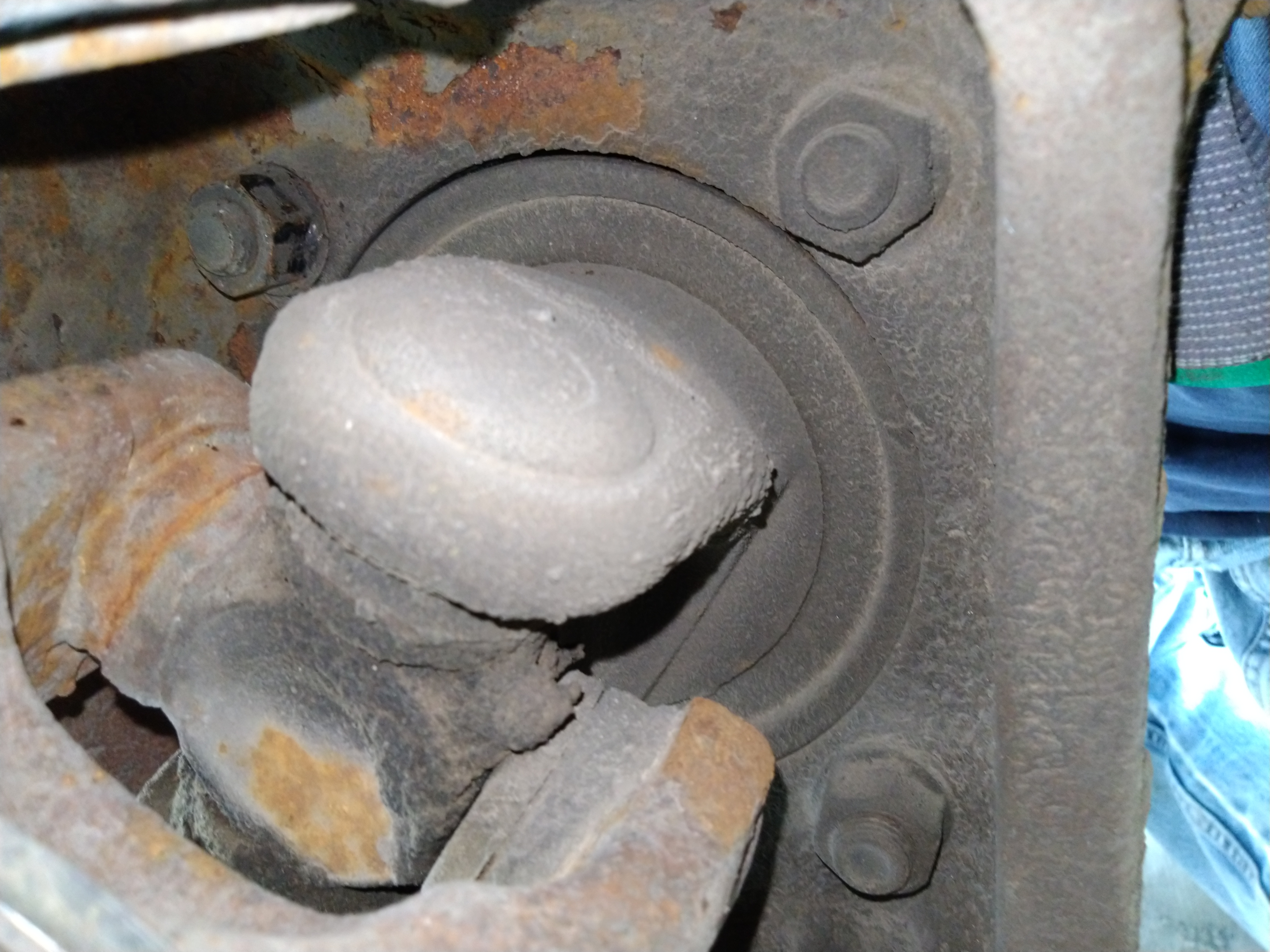
Here's where we'll start, with the axle on a jack stand and the other three wheels chocked.

Here's the old u-joint. I'm replacing it now so I don't have to do it in the middle of the winter when I need my 4WD to work.

I removed the brake caliper and hung it up using a specialized brake caliper hanging tool . . . made from an old wire coat hanger.

The brake rotor was super stuck. I shouldn't have, but I tried hitting it with a hammer to get it off. That is the wrong way. I should have done the bolt method from the beginning. I stuck a bolt through the caliper mounting hole and tightened the nut to push the rotor off. (See photo below.) After the one side broke free, I rotated the rotor 180 degrees and repeated. This worked really well.

With the rotor off, the hub was next. But it could have come off before the brakes. A T-27 torx bit removed the screws. Interesting fact: you see the FORD lettering on the locking hub? The letters are actually vents for the vacuum-operated hubs.

I didn't have to pull too hard to get it out. The grease doesn't look very pretty and it will need to be cleaned off and re-greased. It looks like these auto-locking hubs can't be re-built. If you break the plastic, you may need to buy a new locking hub.

To remove this lock ring, you definitely need a proper set of snap ring pliers. You need to put some muscle in it to spread it wide enough to come off. You may want to do this step later after pulling the axle shaft out. Keep reading.

This is a view of the back of the wheel knuckle. These four nuts need to come off to pull the bearing and hub assembly out.
But first, remove the wheel speed sensor. It needs a 5mm hex wrench.

Be careful not to bend the brake shield. With a little prying and wiggling, the hub will come out.

Here's the big seal that needs to come out. But you can pull the axle shaft out as-is. I made a mistake and tried to pull the seal out first. The seal will come out with the axle.

Here I have a crow-bar stuck through the u-joint space with a socket on the left end for extra leverage. After a bunch of heavy duty yanks like this on the crow bar, the seal popped out along with the axle shaft. It wasn't easy.

I tried my old way of drilling a hole and putting a screw in it and yanking it. That didn't work too well. The screws just popped out of the holes. It was kind of a waste of time.

I bet somebody will tell me that you can leave the snap ring in and pull the wheel hub and axle shaft out all at the same time, and then remove the snap ring later. That should save some effort if you have a big slide hammer.
With the axle shaft out, it's time to replace the u-joints. This next photo is a close-up of the inner clips. They weren't very easy to get out. I took out two clips and figured I'd separate the shaft and then remove the other two clips later.

Here's my setup on the press. A 36mm 12 point socket fit right over the caps. This 20 ton press has come in handy many times. It's so easy to use, I saw that my son had figured it out years ago when I saw a very flat Hotwheels car in the garage.

It took a decent amount of pressure on the 36mm socket to pop this cap out.

Moving to the other two u-joint caps, I was having a harder time and was wondering why the caps wouldn't budge. Then I realized I forgot to take out the retaining clips on this side. Once I took those out, it was easy enough. See that slot cut in, just behind the splines? That's for air to go through to lock the hubs.

After cleaning up the yokes, it's time to put the new u-joint in.

I popped two caps off and put one in the yoke.

Then I put the u-joint through the open end and into the cap. This is why you want the yokes clean because I bet your clean grease will touch the yoke, unless your skill at the game "Operation" is expert level. Then I placed the
other cap over the other end and used my press to push the caps in
place. I made sure to put the grease fitting towards the inside of the vehicle so it's accessible.

After installing all four retaining clips, I gave each side of the yokes a good whack with the hammer to press the caps outward so the u-joint ends don't rub on the caps.
The new dust seal (SKF 16510) looks nothing like what's left of the old one. Not sure what happened there.

Here's the new dust seal installed in the axle. I cleaned off the axle with a wire brush on a drill. Then I greased the entire axle shaft so it would slide on the dust seal. My seal installer set came in handy for this dust seal.

Again, I did things out of order. I installed the axle shaft before installing the big seal. But at least I know it fits in the new dust seal.

Here's the new seal (National 710685) that's going to go on the shaft. I used the seal installer tool to install it on the axle shaft before installing the axle shaft.

Here's the seal installed on the axle shaft before installing it in the hub. I used the same seal installer tool for both steps to install this seal.

This seal installer tool is a must-have for this job. I just had to hit it with a big hammer until it was flush. It didn't take a huge amount of force. It was about what I expected for a seal that size. But I did grease the edge of the seal, for better or worse. I'll probably find out later if that was a bad idea. Maybe I should have used WD40 instead of grease on the outer edge.

I didn't get a new (SKF 5C3Z4) axle hub o-ring to replace the yellow o-ring in this picture. It should be ok though. I greased the surface where the o-ring goes and bolted the bearing/hub assembly back in.

Getting the snap ring back in took many tries. I finally figured out that I needed to hold the axle outward with my crowbar and then it went in. Then I realized I installed the hub without the brake shield. Time to take stuff back apart.
I removed the snap-ring on the first try, unbolted the hub, put the brake shield on, bolted the hub back on, and then God must have accepted my sacrifice and we got the snap ring back on in one try.
It looks like these hubs aren't rebuildable. I'm sure I'd destroy the plastic if I attempted to bend the metal out. The (Dorman 600-249) service kit comes with two o-rings, a gasket, and three replacement screws. I didn't find where the second o-ring goes.
So I added some new grease to the hub and installed it.

From this point, all I needed to finish was re-mount the brake rotor, brake caliper, and wheel.
It took me about 8 hours, a full day of work. It wasn't as bad as I thought. I checked Amazon and saw that I bought the seal install tool almost two years ago. I was dreading this repair, thus the procrastination.


