Monday, September 7, 2020

Front Axle U-joint Replacement on a 2008 F-250

Here's how I replaced the front axle, right side u-joint on my 2008 F-250. I would call it a success. If you need to do the same job, maybe you can learn from my mistakes. Got a day off? This is what I do on my days off to avoid a car payment.

Some tools required: hydraulic press and accessories, T-27 torx bit, 21mm deep socket, breaker bar, #6697 seal install tool, caliper hanger (bent coat hanger), big hammer, grease gun, big snap ring pliers, knee pads, 7/16 bolt & washer & nut to remove the inevitably stuck rotor, 5mm hex wrench, crow bar, and a healthy dose of patience.

Here's where we'll start, with the axle on a jack stand and the other three wheels chocked. 


Here's the old u-joint. I'm replacing it now so I don't have to do it in the middle of the winter when I need my 4WD to work.


I removed the brake caliper and hung it up using a specialized brake caliper hanging tool . . . made from an old wire coat hanger.

The brake rotor was super stuck. I shouldn't have, but I tried hitting it with a hammer to get it off. That is the wrong way. I should have done the bolt method from the beginning. I stuck a bolt through the caliper mounting hole and tightened the nut to push the rotor off. (See photo below.) After the one side broke free, I rotated the rotor 180 degrees and repeated. This worked really well.


With the rotor off, the hub was next. But it could have come off before the brakes. A T-27 torx bit removed the screws. Interesting fact: you see the FORD lettering on the locking hub? The letters are actually vents for the vacuum-operated hubs.

I didn't have to pull too hard to get it out. The grease doesn't look very pretty and it will need to be cleaned off and re-greased. It looks like these auto-locking hubs can't be re-built. If you break the plastic, you may need to buy a new locking hub.


To remove this lock ring, you definitely need a proper set of snap ring pliers. You need to put some muscle in it to spread it wide enough to come off. You may want to do this step later after pulling the axle shaft out. Keep reading.


This is a view of the back of the wheel knuckle. These four nuts need to come off to pull the bearing and hub assembly out. 

 But first, remove the wheel speed sensor. It needs a 5mm hex wrench.


 Be careful not to bend the brake shield. With a little prying and wiggling, the hub will come out.


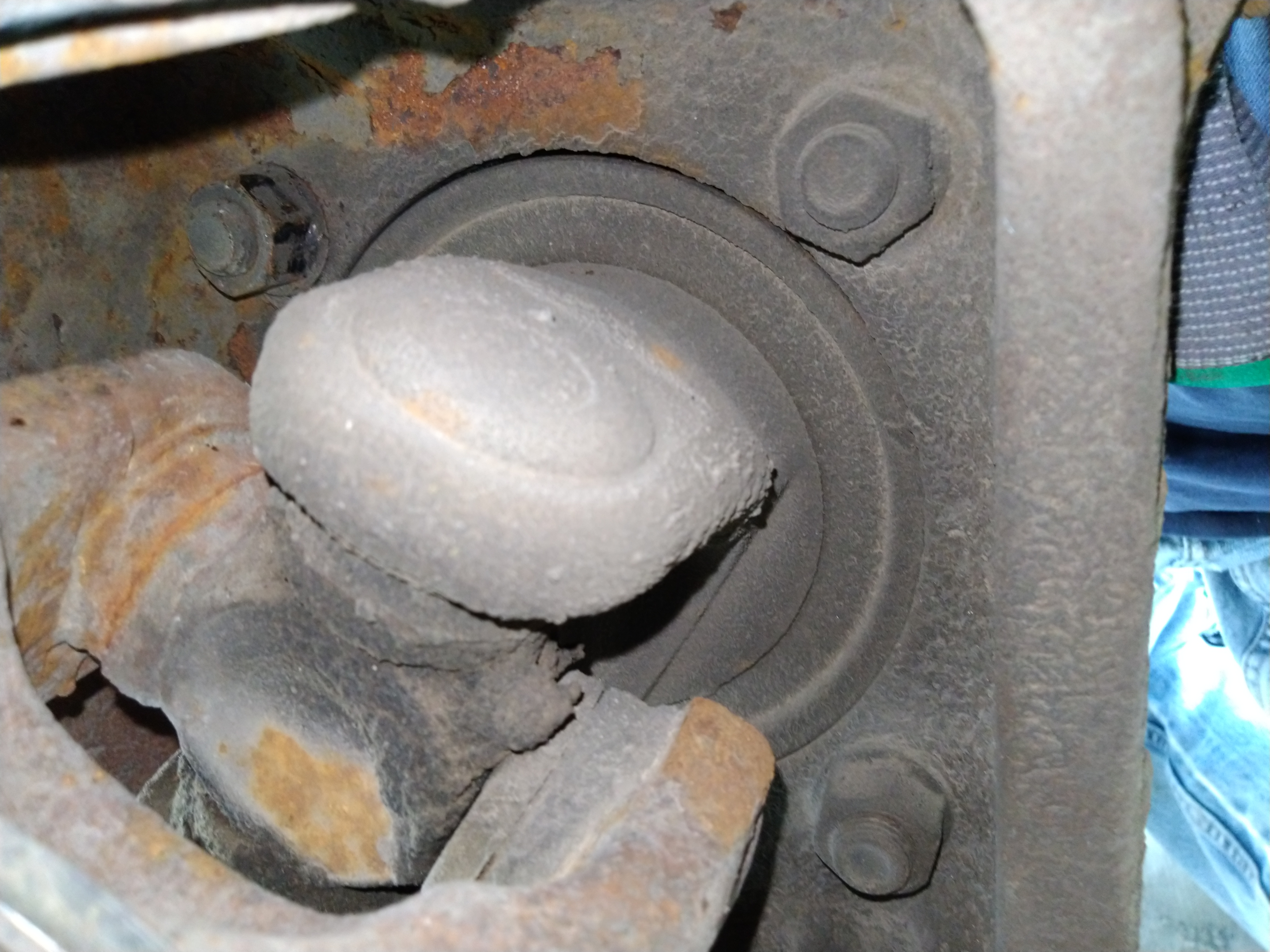
Here's the big seal that needs to come out. But you can pull the axle shaft out as-is. I made a mistake and tried to pull the seal out first. The seal will come out with the axle.


Here I have a crow-bar stuck through the u-joint space with a socket on the left end for extra leverage. After a bunch of heavy duty yanks like this on the crow bar, the seal popped out along with the axle shaft. It wasn't easy.


 I tried my old way of drilling a hole and putting a screw in it and yanking it. That didn't work too well. The screws just popped out of the holes. It was kind of a waste of time.

I bet somebody will tell me that you can leave the snap ring in and pull the wheel hub and axle shaft out all at the same time, and then remove the snap ring later. That should save some effort if you have a big slide hammer.

With the axle shaft out, it's time to replace the u-joints. This next photo is a close-up of the inner clips. They weren't very easy to get out. I took out two clips and figured I'd separate the shaft and then remove the other two clips later.

Here's my setup on the press. A 36mm 12 point socket fit right over the caps. This 20 ton press has come in handy many times. It's so easy to use, I saw that my son had figured it out years ago when I saw a very flat Hotwheels car in the garage.


It took a decent amount of pressure on the 36mm socket to pop this cap out.

Moving to the other two u-joint caps, I was having a harder time and was wondering why the caps wouldn't budge. Then I realized I forgot to take out the retaining clips on this side. Once I took those out, it was easy enough. See that slot cut in, just behind the splines? That's for air to go through to lock the hubs.


 After cleaning up the yokes, it's time to put the new u-joint in.


I popped two caps off and put one in the yoke.


Then I put the u-joint through the open end and into the cap. This is why you want the yokes clean because I bet your clean grease will touch the yoke, unless your skill at the game "Operation" is expert level. Then I placed the other cap over the other end and used my press to push the caps in place. I made sure to put the grease fitting towards the inside of the vehicle so it's accessible.

After installing all four retaining clips, I gave each side of the yokes a good whack with the hammer to press the caps outward so the u-joint ends don't rub on the caps.

The new dust seal (SKF 16510) looks nothing like what's left of the old one. Not sure what happened there.

Here's the new dust seal installed in the axle. I cleaned off the axle with a wire brush on a drill. Then I greased the entire axle shaft so it would slide on the dust seal. My seal installer set came in handy for this dust seal.

Again, I did things out of order. I installed the axle shaft before installing the big seal. But at least I know it fits in the new dust seal.

Here's the new seal (National 710685) that's going to go on the shaft. I used the seal installer tool to install it on the axle shaft before installing the axle shaft.

Here's the seal installed on the axle shaft before installing it in the hub. I used the same seal installer tool for both steps to install this seal.

This seal installer tool is a must-have for this job. I just had to hit it with a big hammer until it was flush. It didn't take a huge amount of force. It was about what I expected for a seal that size. But I did grease the edge of the seal, for better or worse. I'll probably find out later if that was a bad idea. Maybe I should have used WD40 instead of grease on the outer edge.

I didn't get a new (SKF 5C3Z4) axle hub o-ring to replace the yellow o-ring in this picture. It should be ok though. I greased the surface where the o-ring goes and bolted the bearing/hub assembly back in.

Getting the snap ring back in took many tries. I finally figured out that I needed to hold the axle outward with my crowbar and then it went in. Then I realized I installed the hub without the brake shield. Time to take stuff back apart.

I removed the snap-ring on the first try, unbolted the hub, put the brake shield on, bolted the hub back on, and then God must have accepted my sacrifice and we got the snap ring back on in one try.

It looks like these hubs aren't rebuildable. I'm sure I'd destroy the plastic if I attempted to bend the metal out. The (Dorman 600-249) service kit comes with two o-rings, a gasket, and three replacement screws. I didn't find where the second o-ring goes.
So I added some new grease to the hub and installed it.


From this point, all I needed to finish was re-mount the brake rotor, brake caliper, and wheel. 

It took me about 8 hours, a full day of work. It wasn't as bad as I thought. I checked Amazon and saw that I bought the seal install tool almost two years ago. I was dreading this repair, thus the procrastination.

Price breakdown

Moog 374 u-joint: $31.79
Axle dust seal SKF 16510 $7.20
Dorman 600-249 hub lock service kit: $19.08
SKF 5C3Z4 axle hub o-ring $4.92
National 710685 the big seal $31.79
#6697 Seal installer tool $85.26
Exercise patience and gain confidence $priceless

Total: $180.04 + tax and shipping

If I paid someone else to do it, I think it would be around $800.


Sunday, September 6, 2020

Poka-yoke Gone Wrong

Polka yoke?

Poke a yolk?

Pokey yoke?

Po ka yo ke?

"Poka-yoke" is a way to prevent mistakes. One way to do this is to have engineers design parts that can't be assembled incorrectly. Or, in the case of aftermarket auto parts, they make parts that can't even be assembled at all.

Here's an example from a 2007 Ford Freestyle. I needed to replace the passenger side lower control arm because the ball joint was bad. [I'm replacing it with Mevotech part number CMS40148, made in China]. The boot was torn and that caused the ball joint to lose the grease and allow dirt in. Then wear happened and it got enough play that it needed to be replaced. 

The Ford engineers realized that there was a possibility that someone would try to swap sides and use one of the control arms upside down on the other side of the car. I'm not sure why someone would do that, but often times these types of "fixes" are because somebody on the assembly line actually did that. You know that one guy. 

So to prevent this, they added a little metal tab which can be seen behind the right side bolt hole in this picture.

This makes it so the bolt holes won't align if someone attempts to install the wrong side control arm. I can just imagine all these cars stopped on the assembly line with the lower ball joints upside down and they can't mount the wheel knuckles. You can't be machining parts on the assembly line, so this will prevent workers from making that mistake. 

So when I went to install the new control arm, it wouldn't go in. I tried to force it in, but it wouldn't align. I got out the rubber hammer and started whacking it. Still no luck. So I took it out to compare it to the old one. For some reason, Mevotech put the keyway in the wrong place.


You can see the mark from where the tab contacted it. That's nothing a little grinding can't fix. Now it fits!


Too bad Mevotech didn't error-proof their assembly process. But if they had, you wouldn't be reading this.


Friday, July 17, 2020

20 Ton Bottle Jack Won't Jack

The bottle jack in my 20 ton press was jacked. It wouldn't jack. The jack would jack up and down with every stroke of the plunger. The check valve was jacked. I needed to check the check valve to see why it wasn't checking.

The first thing I did was remove the plunger.

The purpose of the check valve below the plunger is to allow fluid to flow from the reservoir into the cylinder when you raise the handle, but not allow it to return to the reservoir. Then when you press the handle down, fluid goes into the small hole which leads to the check valve in the bottom of the jack body.


If this check valve didn't check, then the jack wouldn't jack when you pump the pump.

The next think I did was to loosen the top. This required a good amount of torque, so I put a pipe on the end of my largest pair of channel lock pliers while my bench vice on my truck bumper held the base.


Here's the piston that came out after loosening the top of the jack.  


The body of the jack had a gasket at the base to seal the reservoir. The reservoir cover came out easily by pulling it upwards.

Sure enough, the check ball and retainer were loose in the base of the jack. Looking down into the cylinder of the jack, you can see that I put the check valve back in place with the plastic retainer holding it in place. 

That piece of plastic at about the 2:00 position goes into a hole that's maybe less than a centimeter deep. If I was thinking faster, I could have tapped the hole for the retainer and used a screw to hold a piece of metal over the check ball instead of re-using that plastic piece. That way I wouldn't have this problem again. I think the plastic piece might come out again. 

The hole at the bottom of the above picture goes to the drain valve. It goes to the hole on the left in the picture below to re-fill the reservoir as the piston is lowered. The hole on the right in the reservoir section in the below picture is where the fluid leads to the check valve at the base of the pump.


Re-assembly was easy and straightforward. I filled the reservoir with basic motor oil and checked the operation. It worked like new, no problems. (It's not actually lifting anything in this picture.)


And that's how I saved $40 this evening.

Sunday, November 3, 2019

Furnace Controller Board Repair

Friday morning, my wife said there seems to be an electrical burning smell coming from the vents. I had to go to work and I figured we'd find what it was sooner or later.

That night, it was getting colder than usual in the house, so I checked the thermostat. It was 66F inside, with the heat set to 68. I went to the basement and checked out the furnace. I opened it up and smelled a bit of burning smell. I put the front panels back on and watched the flame ignite properly, but the fan didn't come on and then the flame shut off. I figured the blower motor was bad. I looked at the flashing red LED and it was flashing code 33 - three short and three long flashes.

I took the blower motor out and checked the capacitor. The first step is to always short the terminals together before measuring continuity. I first measured voltage. It was basically at 0 volts. That meant is was safe to check resistance. As the ohmmeter charged the capacitor, it said open circuit. That was good. Then I measured about a half volt on the capacitor. Good. Final check on the capacitance meter showed 9.3 uF, compared to 10 uF on the label. Close enough.

Next, I checked the fan motor. There were several wires coming out of the motor. According to the wiring diagram, white was common, and the rest were for different speeds. Here's where my troubleshooting methods got a little sketchy. I found a spare cord with a plug on it in my electrical drawer. So I attached some terminal ends and then plugged it into the wall. As long as I was careful to not touch the terminal ends or let them contact any metal, or short together, it should be ok.

I set the blower assembly down on the kitchen floor and sat on it to keep it from moving when I connected the power. I connected the common to neutral, carefully plugged it in, then connected one of the other wires to hot. To my surprise, the blower motor ran. I checked all the other wires, and it ran on each one.

So I set the thermostat to a few degrees cooler so it wouldn't turn the heat on and set the fan to "on" instead of auto. I re-installed the blower and turned it on. The fan didn't turn. I measured the flame rollout circuit and it was low resistance, maybe a couple ohms. That checked out, so I took the controller board out of its case.

Furnace: Carrier WeatherMaker 8000
Control board: 1012-83-9410a
I think I found the problem. After a brief internet search, I decided that it was getting too cold inside to wait for an on-line order. I brushed off the burned spot to see if this was repairable. It looked like the copper trace failed and I could just solder in a wire.

Here it is. I soldered in a wire.

After re-assembling everything, I turned on the furnace and the blower motor came on and everything worked as it should. I think I'll need to select a replacement furnace for when this one finally quits. It's at least 18 years old, and it's only 80% efficient. I ran the numbers, and going from 80% to 95% efficiency would save about $80 per year. Over 10 years, that would save $800. So if the price difference is $500, it's justifiable in my mind.

I also read that the PCM (permanent split capacitor) blower motors are only expected to last about 50,000 hours, but the new ECM (electronically commutated motors) are expected to last 90,000 hours. So adding that feature will add about $400 more to the cost of a new furnace. With those two efficiency upgrades it's pushing the furnace cost to around $2063 just for the furnace alone. The additional cost pushes out the return on investment to 10 years. That's assuming I'll need to replace the furnace anyway.

Friday, October 25, 2019

Vision Correction Basics

I never really needed glasses, but knew for as long as I can remember that my right eye didn't focus as well as my left on distant objects. 

A few years ago, I realized that I could no longer focus on things up close. I resisted for as long as I could, but it was futile. I had to get reading glasses. 

I didn't realize that everybody loses focus range in their eyes as they age. It's called presbyopia. The lens loses flexibility with age. In the graph below, the B line is average, and A and C are the upper and lower standard deviations. 
By Hans Strasburger - Own work, CC BY-SA 4.0, https://commons.wikimedia.org/w/index.php?curid=39969617
After I picked out a set of reading glasses, I decided to learn about what the numbers meant. 
For example, reading glasses with +1.50 on the side mean that they magnify 1.5 diopters. 

What is a Diopter?

A diopter is 1 divided by the focal distance in meters. 

Simply put, a set of +1.50 reading glasses will bring the infinity focus point up to 66.7 cm away. 
For convenience, here is a list of diopters vs. focal length.

+0.50 = 2 m
+0.75 = 1.33 m
+1.00 = 1 m
+1.25 = 80 cm
+1.50 = 66.7 cm
+1.75 = 57 cm
+2.00 = 50 cm
+2.25 = 44 cm
+2.50 = 40 cm
+2.75 = 36.4 cm
+3.00 = 33.3 cm
+3.25 = 30.8 cm
+3.50 = 28.6 cm
+3.75 = 26.7 cm
+4.00 = 25 cm
+4.25 = 23.5 cm
+4.50 = 22.2 cm
+4.75 = 21.1 cm
+5.00 = 20 cm

So I put on a pair of +1.00 lenses and tried to focus on something one meter away. I soon realized that I couldn't focus out that far. I began to realize that I may be a little nearsighted. So I decided to take some measurements. 

Measuring My Focus Range

I tried on all my strengths of reading glasses and measured where it would just start to go out of focus for both near and far distances. With this data, I calculated both my nearsighted correction value and my focal range, or eye accomodation. 

Here are the measurements I made, in inches. 


Lenses Near limit, left eye Near limit, right eye Far limit, left eye Far limit, right eye
none 16 14 52 29
0.50 15 12 40 31
1.00 12 11 28 21
1.25 10.5 9.5 20 20
1.50 9.5 9.5 17 14.5
2.50 8 7.5 13.5 12

The far focus limit was pretty approximate with no lenses. As lens power increased, it was easier to see where the far distance started to get out of focus. 

Next, I converted distance to diopters, first converting inches to meters, then to diopters. 

Lenses Near limit, left eye (diopters) Near limit, right eye (diopters) Far limit, left eye (diopters) Far limit, right eye (diopters)
none 2.46 2.81 0.76 1.36
0.50 2.62 3.28 0.98 1.27
1.00 3.28 3.58 1.41 1.87
1.25 3.75 4.14 1.97 1.97
1.50 4.14 4.14 2.32 2.72
2.50 4.92 5.25 2.92 3.28

With this, I could calculate the focus range in diopters and see how I measured up to the graph of accomodation vs. age. 

Lenses Left Range (diopters) Right Range (diopters)
none 1.70 1.45
0.50 1.64 2.01
1.00 1.87 1.70
1.25 1.78 2.18
1.50 1.83 1.43
2.50 2.00 1.97
Average 1.81 1.79

With a focus range of 1.8 diopters, it turns out my focus range is amazingly average for my age. 

Measuring My Nearsightedness

I can take this one step further. With the far focus range vs. lens value, I can calculate the correction needed for distance vision. I simply subtracted my far limit in diopters from the lens value.


Lenses Left correction Right correction
0.00 -0.76 -1.36
0.50 -0.48 -0.77
1.00 -0.41 -0.87
1.25 -0.72 -0.72
1.50 -0.82 -1.22
2.50 -0.42 -0.78
Average -0.57 -0.87

Armed with this information, I could just order a pair of eye glasses online. But do I have astigmatism too? 

Astigmatism

It turns out most people have a bit of astigmatism. That's because the eye lens isn't perfectly shaped. If it magnifies more in one direction than the other, that's astigmatism. It can make objects appear blurry at any distance. If you notice that lines are blurry at certain angles, then you likely have astigmatism. Try printing this focus pattern (link).  

You can find the angle of your astigmatism by viewing the above focus pattern. (It'll work better if you print out the picture from the link above.) See at what angle the lines towards the center are in focus. Horizontal is zero degrees (or 180). Clockwise from your left is positive. That'll be your negative astigmatism angle. If you add 90 degrees, then that's the positive number (keep reading about the angles). 

I noticed that when I try to focus up close, my astigmatism gets worse (to around 0.50), but if I focus far away, then my astigmatism is not noticeable. That's something to keep in mind for when you check your vision.

First Order Aberrations 

A first order aberration is where the focus changes in one direction. If you look at an eye glasses prescription, this would be the number in the cylinder column. It goes along with the number in the angle column. The angle ranges between 0 and 180 degrees because it's symmetrical. If you rotate past 180 degrees, it's like starting over at 0 degrees. 

Zero degrees is to the left of your eye, and increases in angle as you go clockwise. So if you're the eye doctor looking at the patient, it starts at zero to the right of their eye, and goes counter-clockwise. At least, that's how I understand it. I got that from Wikipedia, so you can read the article on astigmatism and see if you understand it that way too.

If you have astigmatism, you can try rotating your glasses to see if you have the correct angle. I ordered a set of test lenses - just a pair of glasses with only astigmatism correction at -0.25 and -0.5 diopters. I didn't think I had much astigmatism, so that's why I ordered those values. Since I ordered them at 30 degrees, I tied my brain in knots trying to figure out the astigmatism angle. Since the handles got in the way while I rotated them, I looked through them backwards. I could tell which direction looked better, but mentally flipping them around and rotating the angle 30 degrees confused me. I thought I had it down until I came up with different answers. 

But I think I got it. If I look backwards through the 30 degree lens and rotate it to 40 degrees clockwise as I look through it, it translates to 10 degrees. Did I confuse you? That's how I felt. 

Higher Order Aberrations

If the focus changes in more than one direction, then that's a higher order aberration. If you printed the above focus pattern and see one angle of lines clearly, and the lines at 90 degrees to it are blurry, you probably have only a first order aberration. If you see an X pattern clearly, but  the plus angle is blurry, you have a higher order aberration. First order abberations can be corrected. Higher order aberration corrections would be extremely difficult to correct, but may be possible with some creative engineering.

Minus vs. Plus Astigmatism Conversion

You can convert negative cylinder to positive cylinder by rotating 90 degrees, and then add back the difference to the spherical number. Every diopter change in cylinder effectually changes a half diopter change in spherical. For example, if you had -1.00 spherical, -1.00 cylinder, at 0 or 180 degrees, then it would be the same as -2.00 spherical, +1.00 cylinder at 90 degrees. 

My "Prescription"


SPH CYL Angle
OD -0.75 -0.25 180
OS -0.25 -0.25 175

I'm going to try this without astigmatism correction first. It's nice that you can order online and have the glasses delivered for less than $15. Then once you verified they work for you, you can order more expensive frames and the nice add-ons. 

Why didn't I just go to the eye doctor and have him write me a prescription? I wanted to see if I could figure it out. Knowledge is power. 

Saturday, October 19, 2019

Ford 3.8 V6 Timing Cover Coolant Leak and Why You Should Always Prime the Oil Pump!

This Thunderbird has had a coolant leak ever since I bought it 15 years ago. I smelled coolant then and pretty much ever since. It has always had a coolant leak. No matter how many leaks I fixed, there was always one more. I think I finally found the one that never goes away.

When they made this engine, they made a mistake. Somebody thought it would be a good idea to drill the threads for the timing cover studs into the water jacket. This creates a leakage path through the threads. It also makes the studs rust.

So here's how this repair went wrong.

I got all the bolts and studs out except for the one that wouldn't turn. I put two nuts together and ran my little Makita impact driver on it to loosen it. That didn't work, so I got out the big impact wrench. I figured that'll do it. It quickly broke the stud off, flush with the timing cover.

I figured I could pry the timing cover off. I got a big crow bar and pried too hard and broke the timing cover, but exposed more of the stud, shown below.


This gave me the opportunity to waste a week soaking it with penetrating oil while attempting to unscrew it. Every try to turn the stud using tightened double nuts was a failure.

I started pulling on it. Then I wedged screw drivers in and pushed on the opposite side. Then I got out the 12 pound sledge hammer and started whacking the opposite side, trying to pry it off. My neighbor Brent came over, kind of concerned, and asked what I was doing. 

I knew he was right when he suggested just getting out the air hammer and chiseling down the timing cover to expose the stud. This thing's coming out in pieces!

After this, I was able to pry it off. 

Re-Assembly

Here's my solution to stop the eternal coolant leak. I put RTV on the threads of the new stud and installed it. I let it cure before installing the new timing cover. (It's the only stud installed in this picture.)


When aligning the camshaft position sensor, you need to set the crankshaft at 26 degrees after TDC. That's right at the edge of this slot that I'm pointing to with a ball point pen.  

My original timing cover had a much better pointer for reading timing than my new cover has. Compare the pointer in this picture to the one in the next picture.

The replacement cover just has an arrow on the surface. I'm feeling short-changed. 

I aligned the crankshaft to 26 degrees after TDC by lining up the slot with the timing mark. I installed and aligned the camshaft position sensor so that the half circle was towards the engine and the edges of the half circle were aligned in the middle of the sensor. Sorry I didn't get a picture of that. 

Why You Should ALWAYS Prime a New Oil Pump

After re-assembling everything, I started up the engine. After every oil change, there's that pause before you get oil pressure. This time, the pause didn't stop. I kept waiting for the oil pressure to build and nothing. The gauge was at zero. I took off the oil filter and started the engine. Nothing came out. 

I removed the oil pump and everything looked ok except there was no oil in it. I learned something there. Without oil in the pump, it will not create sufficient vacuum to draw the oil up from the oil pan. It will just spin and the air will blow past the vanes. You need oil to fill the gaps and create a seal. 

I figured grease would work even better, so I put grease in the oil pump and spun it to make sure everything in there was coated. 

After re-installing the oil pump, I started the engine. This time I heard a ticking noise for a second
until it got oil pressure.

This reminded me of my idea of a bypass electric oil pump. It would be nice to have an electric oil pump run to build up oil pressure before the starter is allowed to turn. 

Was everything good after I got it all back together? Of course not. The water pump went bad and I had to replace it too. 

Saturday, September 21, 2019

Kizen Thermometer Disassembly and Repair

I was looking for a good meat thermometer and chose this one on amazon because of the fast read time and good reviews. Their customer service is excellent and they replaced it under warranty. 

Mine only lasted about a month before it quit working. We noticed that if you open it just enough to turn on, it would work. But that didn't last long until it quit completely. The display would just read "Lo", like this:


So after I received my replacement unit, I figured this would be a great opportunity to do some failure analysis. Here's how I did it. 

First, I removed the battery and then peeled off the face plate. 

Then I unscrewed the five screws that hold the case together. 

The next part was a little tricky. I had to pry the case apart carefully. This end had pegs that snapped together.

As suspected, there's the broken wire. This broke because of an error in assembly. The wire got pinched in the center part during assembly. You can tell because of the flat spot on the black wire's insulation. I have a suggestion for the engineers that made this. If you're going to make a flexible pivot, then you need to choose wires that are more flexible. These wires are too stiff for a lifetime warranty product. You need thinner strand wire, same gauge, to be more flexible and longer lasting.

I soldered the wires together. 

After re-assembly, it works!