Saturday, October 14, 2017

Engineering Mistake? Or Planned Failure? The Fridge.

Was it planned failure, or an engineering mistake? We routinely use copper pipe to carry water, so what would the harm be if the copper pipe was exposed to both air and water? Maybe one of the lowest customer ratings on a refrigerator isn't a good thing for building brand reputation.

I saw a local ad for a free refrigerator. She said it was new, but didn't work, so her husband took it home from work. The pictures on the ad looked good. But then I opened it up. Ugh. It was new how many years ago? She said the landlord was tired of seeing it in the back yard and it had to go. The thing was filthy from sitting outside with the doors open. But I figured I could clean it up and troubleshoot it.

After I got it home I looked up some reviews.

I regret doing business with Maytag – August 21, 2007
Do not buy this fridge – September 11, 2007
MAYTAG BLEW IT – October 4, 2007
MAYTAG ANTI-QUALITY – October 7, 2009
Worst Refrigerator I have EVER bought. – May 15, 2011
Ice 2O - Problems – April 27, 2007
Don\'t buy Maytag! – July 12, 2012
We were happy til now – April 30, 2008
Maytag MFI2568AES - Known control board failure – February 14, 2008
Worthless Junk – November 2, 2007
Ice Flapper Flapping – June 14, 2008

I should have read the reviews first. These reviews got one star, only because there wasn't a way to enter zero stars.

Well, at least I had a starting point to work from. The common failure complaints were the control board or compressor failing. So I decided to give it a shot and plug it in. The thing fired right up with no apparent problems, other than the high pressure line coming out of the compressor wasn't heating up. That meant there was either no refrigerant, or the compressor wasn't compressing.

Since this was a sealed system, I had to buy a tool to recover any remaining refrigerant. The Robinair 40288 line piercing valve did the job. So I attached the valve and evacuated the air out of the lines before piercing the copper. After piercing the copper, my pressure gauge went all the way up to . . . zero. Well, that explains why it wasn't getting cold. There was no refrigerant left.

I pressurized it with air to find the leak. I was all set to spray soapy water to find a leak, but the hissing noise told me I could find it easier than that. The copper line coming off the compressor was routed through the condensation catch pan under the fridge. I guess the hot tubing will help the water evaporate faster. But it'll also corrode the copper pipe. The pan was covered in green copper oxide.

When I cut and pulled the length of copper out, it broke at the leak. The wall thickness where it failed looked really thin.
1/4" OD copper tubing, thinned by corrosion

Here's a section that wasn't in the water. I cut it using a dremel so you could see the normal wall thickness.
1/4" OD copper tubing cross-section, cut with a dremel

I got out the micrometer and this good section was 0.2505" OD. The corroded section was 0.225" OD. That's a lot of thickness lost from corrosion. It appears that copper corrodes significantly when exposed to air, water, and heat all at once.

So I put in a section of 1/4" copper tubing, this time not routed through the water catch-pan. I verified there were no leaks by pressurizing it with 100 psi of air and using soapy water. Then I evacuated the air and let it sit under vacuum over night. Since the fridge may have lost some oil, I took a wild guess and added 5cc of PAG 46. Then I evacuated it again and filled it with about 0.142 kg R134a. At least that's what it's supposed to be. My cheap scale doesn't read down to grams. I stopped when it said -0.14 kg.

The fridge works now and has been running for a day. But the problem could have been avoided if the engineers had done some reliability testing on the new design, like measure how copper corrodes with air, water, heat, and time. Do some accelerated stress testing and calculate the lifetime based on the extreme use conditions.

Do Washing Machines Eat Socks?

Do washing machines eat socks? Yes. Yes, they do.

They'll deny it, but we caught this one with the evidence. On top loading washing machines, there's a gap between the top of the basket and the top of the frame. Small items like socks can easily fit through there and get sucked into the drain pump.

If that happens, it can jam the drain pump like this one and cause the washing machine's motor to stop turning.

This sock was jammed in there so tightly that the drain pump wouldn't turn. This picture is after we played tug-of-war with the sock and the pump. It was in there so tightly, I had to use two hands on the needle-nose pliers while my friend Rex pulled on the pump.


The sock must have gone over the top of the drum and went right down the drain tube into the drain pump. 

The motor didn't appear to have sustained any damage and the washing machine is fine now. I can't say it learned its lesson though. Once they get a taste for socks, there may be no going back. 

Saturday, September 23, 2017

4WD Truck Pulls Left Then Right Then Left Then Right

The Problem

Every once in a while, my truck would pull left then right, then left, then right, and eventually settle down and not do it again for weeks. It started out as a very faint pull to one side, then the other. I thought something was wrong with the power steering gear box. Then I noticed it would sometimes start doing this after going around a corner. This week, I almost hit a curb going around a corner because the steering didn't return to center like it normally did. I had to force the steering wheel back to center.

Here's a video of the truck pulling left then right.  I was doing my best to keep it in a straight line, but it looked like I was weaving a little:


Diagnosis

So I took a look under the truck. I found nothing wrong with any of the steering linkages. I had my son turn the wheel left and right as I watched the steering linkages move. Still nothing wrong. Well, my axle dust shields were shot, but that wasn't causing the problem.


I then jacked up the front axle so the front tires were both off the ground. I turned the manual hub lock on the passenger front wheel and found that the front right wheel would turn just fine as long as the steering was pointed straight. But when I turned the wheel either right or left, the wheel would jam. This was because two of the four joints on the U-joint were binding up.

Why the U-Joint Causes the Problem

This truck is a 2008 Ford F-250 with a solid front axle with U-joints at the wheels. When it's not in four wheel drive, the hubs are unlocked and the front axle doesn't rotate, so the U-joints stay in the same position and don't rotate when the truck is rolling.

When the wheels steer left or right, you can have only two of the U-joint bearings pivot with the steering while the other two don't turn. The axle may stay in the same position while driving as long as it's not in 4WD.

The problem shows up when the axle rotates a quarter turn and the seized U-joint bearings are now in the vertical instead of horizontal position. This makes steering more difficult and causes it to pull to one side or the other. Then when the axle rotates another quarter turn, the problem magically goes away and doesn't show up again for a while.

It's My Fault

I've had this truck for a year and a half and hadn't greased the U-joints in the front axle . . . ever. So I cleaned off the grease fittings and pumped some grease in the U-joints.

For a test drive, I kept the front right hub locked manually, but the switch on the dash was not engaged in four wheel drive. As I pulled out of the driveway, the steering wheel would pull as the wheel rotated. Then it stopped pulling as the grease worked its way into the U-joints.

This wasn't a Ford problem. It was because of bad ownership. The truck wasn't properly maintained and the U-joints lost their lubrication. This steering problem can occur on any similarly configured 4WD pickup with U-joints on the front axle, be it Ford, Dodge, Chevrolet, or other.

Monday, September 18, 2017

What's That Scraping Noise?

After replacing the shocks, I heard a new scraping noise while driving. I'll show you the picture in a minute. 

Since replacing the shocks is pretty easy, it wasn't a blog-worthy project, so I didn't take any pictures. One thing I found wrong was that the front shock top mounts were loose. Maybe that contributed to the shake. I also have a wheel that needs to be balanced, but the new shocks make it ride better.

After installing the shocks, I drove to the corner gas station to fuel up. I was headed to a family get-together about 45 minutes away. After pulling out of the gas station, I rolled down the windows and heard a scraping sound. It wasn't loud, but that noise wasn't there before I changed the shocks. I figured I had better take a look under there and see if I can see what it was. 

I actually debated whether or not I should stop and check, or just keep going. It's a good thing I stopped. 


So I was using a wrench to hold another wrench from getting jammed in the spring while I loosened the rusted bolts on the top of the shocks. It kept dropping, so I'd grab another wrench on the ground and use it. I must have missed the fact that that wrench didn't hit the ground. I also don't have a dedicated place for that wrench since it's not in a set. So that's why I missed it when I put the tools away. 

It's kind of like life. You can see if you can fix those small annoyances, or you can ignore them and risk them turning into much bigger problems. 


Sunday, September 10, 2017

Floppy Subaru Visor Failure Analysis

This visor from this 2008 Impreza wouldn't stay up. So after getting a new one, I decided to take it apart to see what failed.

The mounting end can just be pulled out.


After cutting the vinyl cover open, I pried apart the clip.


To separate the two halves, I pried around the edges.


There it is. The plastic surrounding the metal rod had broken. The black metal part that's in the visor below is springy. It squeezes the rod. It keeps tension on the rod to keep it in place. I had to pull the broken parts out before I could get the two halves to separate without breaking it.


Here's the inside of one half.

And here's the inside of the other half.


Tuesday, August 1, 2017

Do your shoelaces keep coming untied?

Years ago, when I was a teenager, my Father noticed that I was tying my shoelaces wrong. He said that if I tied the first knot the other way that the laces would lie across the shoe instead of lengthwise.

It was humbling to know I'd been doing it wrong all these years.

I was too stubborn and proud to change my ways. I didn't care if the shoelaces were a little crooked. I would rather go around with crooked shoelaces than admit I was wrong. Besides, I wasn't going to admit I was doing something wrong that most kindergarten students have already mastered. It was working for me, or so I thought.

Little did I know that there's a strong form and a weak form of the knot. I just figured that it was the shoelaces on certain shoes that made them come untied so often. Several times a day I would have to stop and re-tie my shoes. I should have had listened to my older, wiser, and more experienced father. I don't know why that memory stuck with me, but I'm glad it did.

There are many videos on the internet showing that the incorrect form of the knot goes lengthwise, but it can still be unclear if you're doing it wrong. Here's my suggestion on how to tell if you're tying the strong or weak form of the standard shoelace knot.

Pull the loops out - not like you're untying your shoes - more like you're trying to cause trouble.


Then you're left with that dreaded double knot that takes several more seconds to undo so you can get your shoes off. Examine this knot. If it's a square knot, you're tying your shoes correctly. If it's a granny knot, then you're doing it wrong.

The granny knot is not symmetrical. You're doing it wrong!
The square knot is symmetrical. Congratulations, you're doing it correctly!

One TED video explains that the way to fix it is to simply go the other way around the loop. Hmm. That muscle memory is really hard to re-learn. You can get the same results by changing the direction of the first knot. I think that's much easier.

Correctly tied shoelaces

I told my mom that I was tying my shoes incorrectly. She was shocked. "Who told you that? I was the one who taught you how to tie your shoes!", she responded incredulously.

Lastly, I'd like to thank Ian for the neat new way to tie the same knot.


Wednesday, June 28, 2017

Ford P1443

I had the code P1443 come up on my 1996 Thunderbird way back in 2003 or 2004. I replaced the evap canister purge flow sensor. The problem went away for nearly 200k miles. Now it's my daughter's car and the same code came up. So I measured the resistance between the power and ground pin. It was between 500k ohms to 1.5M ohms, different each time I measured it. The replacement part measured 96 or 97 ohms. Bingo! The old sensor had failed.

The sensor is located on the passenger side under the headlight. I got to it from underneath. It was kind of tight getting in there, but not so tight that I had to take anything apart to get to it.

Here's the wiring diagram for the plug. I got it from this website.


Here's a picture of the replacement part, CP509. The funny thing is, the local auto parts store had it in stock, but their online catalog didn't have it listed. You could find the Thunderbird under the compatibility tab, but you couldn't look it up in the catalog.

The pin on the left in this picture is the ground pin. The top right is the power, and the bottom right is the output voltage.

Friday, June 16, 2017

DIY Homemade AC Service Machine

Here's one of life's lessons I take a while to learn.
Just because I can, doesn't mean I should.
But just because I failed doesn't mean it was a terrible idea, because I learn from my failures, even when they cost money.

Sometime around 1997, I spent about $1000 trying to install an air conditioning system in a 1981 Ford Econoline E100. That thing had a 4.9L straight six and a manual transmission. We called it the big brown van. We had some good times taking it camping and on vacations. But I made two major mistakes on that AC system.  
  1. I thought it would be a good idea to have the refrigerant enter the bottom of the condenser and exit out the top. I didn't know that the refrigerant turned from a gas into a liquid inside the 'condenser'. Its name should have been my first clue. Having a hard time getting the fittings and hoses to fit right should have been my second clue. You want to send the liquid refrigerant to the evaporator. Since liquid is heavier than gas, the bottom tube is the exit.
  2. My second major mistake was thinking that the oil stayed in the compressor. I didn't realize that the oil circulated in the system along with the refrigerant, so I didn't add oil to the system and the compressor made a lot of noise and had a lot of vibration.
So even though I had a thermodynamics class in college, it still didn't prepare me to work on a real-life air conditioning system. There are some real-world need-to-know things they just don't teach in class.

So this is for all those out there who are like me that want to do it themselves and can benefit from learning from my mistakes.

Too many people try to fix their own AC by just adding a can of R134A. Usually, when the refrigerant is low, it's because it leaked out. Sometimes adding a can works . . . for a while. Other times, the refrigerant just leaks out, or only lasts a day. Sometimes the system gets overcharged. Sometimes, there's another problem in the system and adding refrigerant would be a mistake.

Building My AC Service Tool


Since I didn't want to pay shop rates for my AC service, I made a contraption to service car air conditioners. With it, I can
  • Recover refrigerant
  • Evacuate the system
  • Recharge with the exact amount of refrigerant needed
- all without having to disconnect any hoses. That way, no air gets in the system.

To repair leaks or replace components, we don't want to just open the system and let the refrigerant out. That's not only wasteful, it's bad for the environment. We need to be able to recover the remaining refrigerant. So I picked up a recovery unit and a couple recovery tanks from the local classified ads.

I got my vacuum pump from Harbor Freight. The 30 lb refrigerant containers can be obtained from the local auto parts stores. I found a refrigerant recovery machine and a 50lb digital scale in the classifieds.

Most of the fittings and valves are 1/4 inch. For the first couple years, I was having trouble with leaking valves. The 1/4" air valves were wholly inadequate for this type of service. I had to replace them all with 1/4" valves made for water. Although they were much more expensive (around $11 each), they worked.

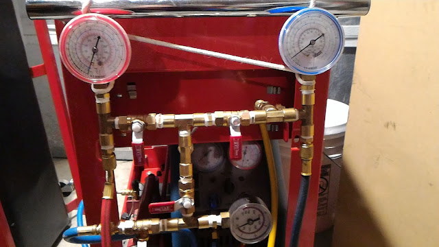
Here's the schematic diagram of the AC service machine.

I bought a manifold gauge set and took it apart to use the hoses, service port valves, and gauges shown here. I also bought a few more hoses connect the vacuum pump, recovery tank, recovery unit, and refrigerant canister. I got all the other brass fittings and adapters at the local hardware store.


Since I had a red toolbox on wheels and it was the perfect size for it, I loaded all the components onto it. On the other side, I have the refrigerant recovery tank. The recovery unit and vacuum pump are on the bottom shelf.

Operation

Setting up the Machine


  1. Connect the refrigerant canister to the charging port (center rear in the photo). 
  2. Close the charging port adapter valves. Open all the valves except the recovery machine's input valve stays closed.
  3. Vacuum down the system.
  4. Close all the valves. 

Recovering Refrigerant

  1. Connect the red hose to the high side service port, and the blue hose to the low side service port. Turn the service port valves clockwise to open them. The high and low side gauges should read pressure if there's any refrigerant remaining in the AC unit being serviced. 
  2. Turn on the recovery machine. Its intake valve should be closed at this point.
  3. Open the valve behind the low side gauge. Ideally, I should have an oil separator unit between this valve and the recovery machine, but I don't. So I just recover slowly to avoid pulling oil out of the system. 
  4. Slowly open the input valve on the recovery machine. Keep the pressure less than 20psi. There are other steps unique to this recovery unit, so I won't go into detail on that here. 
  5. Stop when the input valve is fully open and the gauge reads -10 inches Hg or greater vacuum.
  6. Purge the recovery unit into the recovery tank.
  7. Remember to close the valve on the recovery tank. 

Evacuating the System

  1. Shut all valves. 
  2. Turn on the vacuum pump. 
  3. Open the valve to the vacuum pump (on the lower left of the above picture where the blue hose on the left comes in).
  4. Open the valve above the vacuum gauge (bottom center valve).
  5. Open the valve to the left of the low side gauge and the valve going to the refrigerant tank hose. The refrigerant tank's valve should still be closed at this point. 
  6. When most of the gas is evacuated, also open the high side service port valve and the valve to the right of the high side gauge. 
  7. After enough time has elapsed, shut the valve going to the vacuum pump. The gauge should not move. At this point, we have evacuated all the air and gasses from the air conditioner and my AC service machine. 

Charging the System

I usually dump the refrigerant into the high side service port. Here, I need to pause and think it through so I don't make mistakes.
  1. Close the service port valve at the high side service port. 
  2. Close both valves on either side of the vacuum gauge. Disconnect the vacuum hose from the vacuum pump so that it doesn't suck oil out of the vacuum pump. 
  3. Close the valve to the left of the low side gauge. 
  4. We want to put refrigerant into the hoses, but not in the air conditioner yet. So I open the valve on the refrigerant tank. It goes all the way up to the service port, waiting to go in the system. 
  5. Weigh the refrigerant tank and note it. Subtract the weight of the refrigerant we want to put in, and that's where we stop when it gets to that point on the scale. 
  6. Open the high side service port valve and watch the scale weight go down. If it doesn't deposit the full charge, then start the AC and slowly and intermittently open the valve to the left of the low pressure gauge to allow small amounts of refrigerant into the low side. We don't want to go too fast and send liquid refrigerant into the intake of the compressor. 
  7. Close the valve on the refrigerant canister. If I'm going to store the machine for a week or more (and that's usually always the case), I recover the refrigerant in the hoses so it doesn't leak out. 

Enjoying the Results

The machine works great. 

Troubleshooting

The system may be low on refrigerant if the high side pressure is low and the low side pressure is too low and the compressor cuts off even when the fan is on high.

If the high side pressure is normal, but the low side is low, that could be a symptom of a clogged orifice tube (or expansion valve). In this situation, many people may assume that the system is low on refrigerant and add more. The excess refrigerant makes the high side too high pressure, resulting in loss of efficiency and not solving the problem.

There are other sources of information on troubleshooting, so I'll stop here.

Monday, May 22, 2017

Ford & Mercury 2.5L V6 Rattle at Start-up

If you have a Ford product 2.5L V6 that makes a rattling noise on start-up, you may have a loose timing chain. It's not a problem you want to ignore. The rattling is the chain flapping around. It can rub on the oil pump. It can break off the plastic timing chain guides. Then the timing chain can wear into the aluminum guide. The chain can also skip a tooth or more and get out of time.

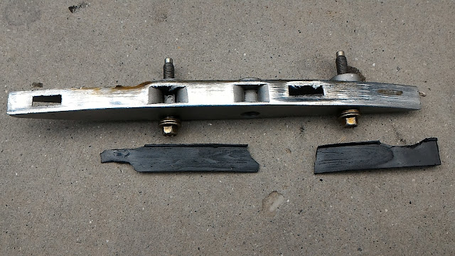
Here's where the timing chain rubbed on the oil pump. (I took out the chain guide.)

Here's a picture of a tensioner against a timing chain guide (not in the engine). The piston is actuated by oil pressure. But the ratcheting rod keeps tension when there isn't enough oil pressure.

If that ratcheting rod fails, then it will rattle pretty badly on start-up. That happened in my case. Here's a picture of the original tensioner on the right, and the failed one on the left. The ratcheting mechanism totally failed and allowed the rod to go back into the tensioner.


This allowed the chain to get loose because the tensioner's piston was allowed to retract.


That allowed the chain to slap against the chain guide, breaking the plastic off and rub into the aluminum chain guide.


Then the plastic parts got chewed up by the timing chain and spit into the oil pan where they clogged the oil pickup tube.


I had put RTV black between the plastic and aluminum parts of the chain guide when I replaced it the first time in this blog entry. So when it came off, the RTV did too and helped clog the oil pickup. The oil light was flickering at idle. Then it came on steady on the highway and stalled in the right lane in heavy traffic. It took five minutes before some nice guy pushed her off to the side of the road so she wasn't blocking traffic anymore. I was on my way and found her safe on the side of the road. The Cougar actually started again and we drove it off the freeway.

Loading it onto the dolly to tow it home was an interesting experience. Let's just say we got it on the dolly with maybe 10 guys lifting the front end back into its proper place on the dolly. I wish I had video of that, but I didn't think about it at the time.


Update 3 June 2017

I just put a new chain guide in. To make sure the tensioner wasn't too loose, I pried gently on the tensioner guide to take up all the slack, then released the pry bar and made sure there was no slack on the ratcheting rod. After I put it all back together, it actually still runs. I drove it around the block and it seemed fine. Miracles still do happen! Maybe the Prolong I added a long time ago helped.

The entire job took maybe 16 hours, basically two Saturdays. I had to take off the upper intake, the valve covers, the exhaust Y pipe, the oil pan, the passenger side engine mount, coolant overflow, power steering pump, and the alternator bracket to get the timing cover off. The alternator is crammed in there pretty tightly with not much room to get at the bolts.

Update 7 June 2017

Well, it lasted less than 10 miles before the engine started making a squealy tapping knocking sound. I took the drive belt off, so it's not that. But you probably figured that would happen when I told you about the oil light coming on.


Monday, April 24, 2017

Toguard Backup Camera Replacement?

A year ago, I bought a Toguard 5" Android dash cam with a backup camera. Several months ago, the backup camera died. Here's a picture of the camera that came with it (from the Amazon listing):
The camera that came with the Toguard DVR mirror

I figured I'd search Amazon for a replacement camera. I found this one and thought it was the same.
Replacement backup camera
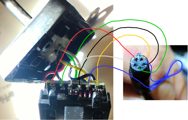
I plugged it in and . . . nothing. Then I attached the power wires on the new camera. Still nothing. So I did a quick resistance check and saw that they were not wired the same. That kind of upset me, so I took it out on the cameras - both of them. I had to take them apart and see how each was wired. So on the long-shot that somebody's looking for a wiring diagram for both of these backup cameras, here ya go.

Toguard backup camera, disassembled
The wire from the camera to the DVR mirror is a five conductor cable, with a foil shield.

Toguard backup camera plug

When checking the old camera, I found that it wasn't the camera that failed, but the cable. There were multiple breaks in the line, but nothing obvious from the outside.


As far as I can tell, here is how the original backup camera for the Toguard DVR mirror was wired to the 2.5mm four conductor plug:

Tip: Red wire labeled DC, 5.75V power
Ring: White wire labeled DM, Video (signal ground, maybe?)
Ring: Green wire labeled DP, Video (signal high, maybe?)
Sleeve: Black wire labeled GND, Ground/reverse signal
____________________________________________________________________________

The replacement camera appears to be wired as follows:

Tip: Red wire, camera power
Ring: yellow wire, video signal
Ring: +12V power and white wire to LEDs
Sleeve: Ground wire and black wire to LED ground

Comparing the two wiring diagrams, you can see that plugging this into my DVR mirror and connecting power to the new backup camera was a bad thing. That put +12V on the video input. Keep in mind that the Android tablet only runs on +5V. I think the backup camera input is now fried.

Replacement backup camera plug
Now, look at the above picture. Can you think of any reason why it would be necessary to connect +12V to any tablet device's input? That doesn't make any sense to me.

Replacement backup camera, disassembled

Replacement backup camera, showing the image sensor on the circuit board
 Although the outside and the plugs looked very similar, these two cameras were in fact, very different.


Monday, April 10, 2017

1998 Accord Won't Start - Why you should RTM

My friend brought his car over because he was having problems where it sometimes wouldn't start. I said I'd take a look at it and didn't see anything obviously wrong. The OBD-II scanner didn't show anything wrong either. So I told him to just wait until it wouldn't start again and then we'll troubleshoot it.

It didn't take more than a couple days before he said it wasn't starting again. He tested for spark in that wasn't the problem. I then told him to open the throttle about 1/4 of the way and crank it for about five seconds, then smell the exhaust. He didn't smell any gasoline. Starting fluid helped for a bit.

I had him get down by the fuel tank and have someone turn the key to the on position. He heard the fuel pump run for a couple seconds. Check.

Our task was to find why the fuel injectors weren't firing. I had my OBD-II scanner plugged in, but it wasn't talking to the computer. I didn't see any relays labeled for ECU or PCM or the like. No fuses were blown.  I couldn't figure out why the engine computer wasn't powering on. I was turning the key off and on, watching the LEDs on the OBD-II adapter and saw no signs of communication.

It was then that I noticed a little green light on the dashboard shaped like a key. When I turned the key to on, the light went on, then started flashing. "Hey, do you have a spare key for this thing?" I put the other key in and turned the key to the on position. The light came on, then went out and stayed out. "Hey, put that air intake back together under the hood." It fired right up.

And that's why you should read the owner's manual.

Picture credit: https://www.youtube.com/watch?v=hpG3Sazz3GA

Thursday, March 30, 2017

Replacing the screen on a ZenFone 2 Laser

The kid was having a bad day with his motorcycle repair. And then he dropped his phone, shattering the digitizer and breaking the LCD display and making his bad day even worse. Luckily for him, I had a spare phone. The spare phone was another ZenFone 2 with better specs. I let him borrow it while we waited for the replacement screen to arrive. 

It only made sense to get a $30 replacement display with the digitizer included to fix a $230 phone.


I watched a youtube video that showed how to disassemble the phone. The first parts were easy. Getting the back off, removing the battery, and the dozen screws (don't forget the one under the security sticker!) was easy. The back lifted right off after getting the screws all out.

The speaker module was stuck in with adhesive, so a little pulling got it out without too much trouble. The vibration motor came out without having to deal with any adhesive.

Watch a video that shows you how to remove the ribbon cables for the display and digitizer. You'll want to flip up the little plastic bar before sliding the connectors out.

Now, I don't know why the video shows them prying on the power switch. You don't need to pry on it or even remove it. Just leave it where it is. You can see on the left, it's still there in the picture below.


There is a white thermally conductive pad that you'll need to save or replace. I just added some thermal compound and stuck it back on when it was time to reassemble it.

If you've done this much, you're in for a treat. I recommend safety glasses for this next part. Prying on glass that's glued down could send tiny glass fragments flying. The best place to start is on the corner that's shattered. That way, you can get underneath the glass and separate it from the phone body. There's glue all the way around the entire edge. Separating the display from the phone is a tedious ordeal that will try your patience. And just now I realized that I should have used a hair dryer to heat it up. I don't do these very often, thankfully.


After getting the phone and screen separated, I removed the remaining adhesive from the phone because I didn't want any uneven edges. I'm sure glad I did a test fit before gluing the new screen in. I had to scrape out a corner so the new glass would fit in. The phone was bent on the corner that it dropped on, so I also had to bend that corner back.

You can see on the old screen (top) that the top right corner is bent. That's where the phone landed. The replacement screen (bottom) matches the old one.


I realized that the new screen didn't come with any replacement adhesive. I wasn't going to wait for an order of adhesive strips, so I decided to use contact cement. It's not the best idea, but it seems to be holding, at least for now.

Success! It worked! I got your phone fixed. Do you want to switch back? Nope, he said. "This one's battery lasts much longer." And that's why I like to have a spare phone, just in case.